Spliced connector assembly

A technology of connectors and insert rods, which is applied in the field of splicable connectors, and can solve the problems of inflexible use and inability to meet the number of different wires.

Inactive Publication Date: 2016-03-02
镇江市京口润明微波器械厂
View PDF7 Cites 2 Cited by
  • Summary
  • Abstract
  • Description
  • Claims
  • Application Information

AI Technical Summary

Problems solved by technology

In the existing design of the connector, the number of pins at the male end is fixed, and the number of jacks at the female end is also fixed, and in the course of use, various circuits with different numbers of wires will be encountered, making the existing The designed connector has limitations in the use process, and the use is not flexible enough to meet the needs of different numbers of wires

Method used


Image

  • Spliced connector assembly
  • Spliced connector assembly
  • Spliced connector assembly

Examples


Embodiment Construction

[0020] The technical scheme of the present invention will be described in further detail below in conjunction with the accompanying drawings and specific embodiments, so that those skilled in the art can better understand the present invention and implement it, but the examples given are not intended to limit the present invention.

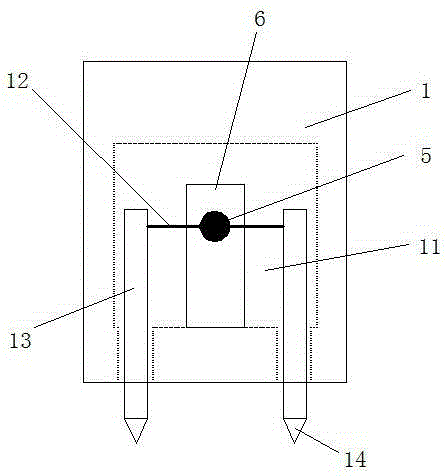
[0021] Such as figure 1 , 2 As shown in and 3, a splicable connector includes a paired cuboid male end housing 1 and a cuboid female end housing 2. Generally, the male end housing 1 and the female end housing 2 are plastic shells body. Wherein, at least one contact pin 3 is arranged at equal intervals on one surface of the male end housing 1 , and a corresponding insertion hole 7 is arranged on one surface of the female end housing 2 . It should be explained that in order to distinguish the different positions of the components, the names of the same components are distinguished by "male end" and "female end".

[0022] Such as figure 1 with ...


PUM


Abstract

The invention discloses a spliced connector assembly, which comprises paired rectangular male end shell and rectangular female end shell, wherein at least one contact pin is arranged on one surface of the male end shell at equal intervals; corresponding inserting holes are formed in one surface of the female end shell; a male end slide chute and a male end button are arranged on one surface of the male end shell; the male end button can move along the male end slide chute; a male end side inserting hole is formed in one side surface of the male end shell; a corresponding male end side inserting rod is arranged on the opposite side surface; the male end side inserting rod is connected with the male end button; a male end cavity for placing the male end side inserting rod is arranged in the male end shell; and the male end side inserting rod extends out of the male end shell or is hidden into the male end cavity by moving the male end button. The spliced connector assembly can be spliced to meet the requirements of wires with different numbers, and is relatively flexible to use and convenient to switch.

Description

technical field [0001] The invention relates to a spliceable connector. Background technique [0002] Connectors are also called connectors, which transmit current or signals. Generally speaking, the side with needle or rod-shaped pins is the male terminal (referred to as the male terminal), and the side with the jack is the female terminal. (referred to as the female end). In the existing design of the connector, the number of pins at the male end is fixed, and the number of jacks at the female end is also fixed, and in the course of use, various circuits with different numbers of wires will be encountered, making the existing The designed connector has limitations in the use process, and the use is not flexible enough to meet the needs of different numbers of wires. Contents of the invention [0003] In view of the above problems, the present invention provides a splicable connector, which can be spliced ​​with each other to meet the requirements of different numbers o...

Claims


Application Information

Patent Timeline
Patent Type & Authority Applications(China)
IPC IPC(8): H01R13/20
CPCH01R13/20
Inventor 严步云
Owner 镇江市京口润明微波器械厂
Why Eureka
Try Eureka