
Thermoelectric module and manufacturing method thereof

A technology of thermoelectric modules and manufacturing methods, which is applied in the manufacture/processing of thermoelectric devices, thermoelectric device components, thermoelectric device node lead-out materials, etc., and can solve the problems of temperature sensing performance degradation, insignificant temperature difference, and limited film thickness and other problems, to achieve the effect of improving sensitivity, increasing electromotive force, and improving thermal electromotive force

Inactive Publication Date: 2016-03-02
SAMSUNG ELECTRO MECHANICS CO LTD
View PDF1 Cites 10 Cited by
  • Summary
  • Abstract
  • Description
  • Claims
  • Application Information

AI Technical Summary

Problems solved by technology

However, when the semiconductor element is formed in a thin film form, the temperature between the heat absorption side and the heat dissipation side is balanced in a short time due to the thin thickness in terms of process characteristics, so that the temperature between the heat absorption side and the heat dissipation side is balanced. The temperature difference between
As such, the thin-film type thermoelectric module has the disadvantage that the thickness of the thin film that can be formed is limited, so that the temperature difference between the heat-absorbing side and the heat-radiating side is not significant, and thus the thermoelectromotive force cannot be increased, resulting in a decrease in temperature sensing performance

Method used


Image

  • Thermoelectric module and manufacturing method thereof
  • Thermoelectric module and manufacturing method thereof
  • Thermoelectric module and manufacturing method thereof

Examples


Embodiment Construction

[0042] The purpose, specific advantages and novel features of the present invention will become more apparent through the following detailed description and preferred embodiments in conjunction with the accompanying drawings.

[0043] Before this, it should be explained that the terms or words used in this specification and claims should not be interpreted as generalized and dictionary meanings, but should be based on the inventor's ability to explain his invention in the best way. The principle of properly defining the concept of terms is interpreted as the meaning and concept in accordance with the technical idea of ​​the present invention.

[0044] In this specification, when assigning reference numerals to components in the respective drawings, care should be taken to assign the same reference numerals as much as possible even if the same constituent elements are shown in different drawings.

[0045] In addition, terms such as "first", "second", "one side", and "another side...


PUM


Abstract

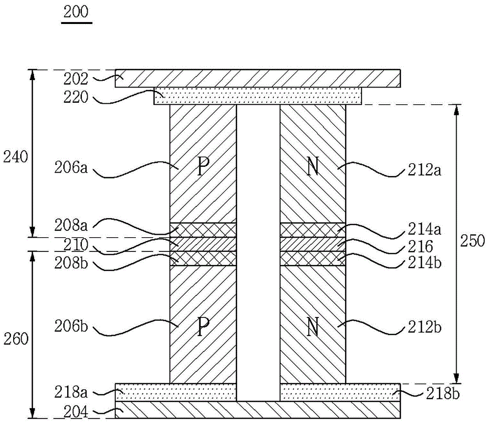
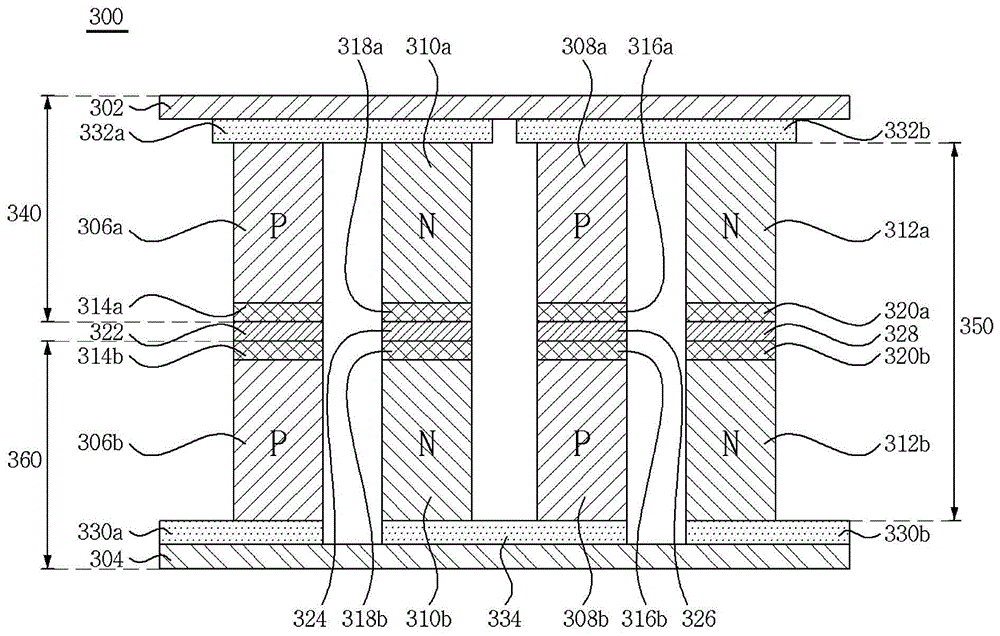
The invention discloses a thermoelectric module and a manufacturing method thereof. The thermoelectric module comprises a lower thermoelectric module, wherein p type and n type semiconductor elements are arranged on the upper part of the lower insulation substrate along the horizontal direction; an upper thermoelectric module, wherein p type and n type semiconductor elements, which are electrically connected, are arranged on the lower part of the upper insulation substrate along the horizontal direction; and a joint part, which joins the p type semiconductor element in the upper thermoelectric module and the p type semiconductor element in the lower thermoelectric module and also joins the n type semiconductor element in the upper thermoelectric module and the n type semiconductor element in the lower thermoelectric module. Through the joint part, the upper part thermoelectric module comprising a thermoelectric semiconductor element and the lower part thermoelectric module comprising a thermoelectric semiconductor element are joined together, thus the thickness of thermoelectric semiconductor element part is multiplied by two; so the temperature difference between two ends of the thermoelectric semiconductor element part is increased, the electro-dynamic potential of the thermoelectric module is increased, and when the thermoelectric module is used as a temperature sensor, the sensitivity of the sensor is improved.

Description

technical field [0001] The invention relates to a thermoelectric module and a manufacturing method thereof. Background technique [0002] Temperature sensors are essential components for monitoring the temperature of household appliances such as ovens and refrigerators. In addition, in industrial equipment, monitoring such as accurate temperature maintenance and adjustment can also be said to be a necessary condition for the production of high value-added products. Therefore, it can be said that a temperature sensor for monitoring temperature is a necessity in almost all fields including daily life and industrial fields. There are various types of temperature sensors currently on sale depending on the temperature range and resolution to be measured. [0003] Thermoelectric phenomena can be divided into two major technologies, which are classified into cooling technology using the Peltier effect and energy harvesting technology using the Seebeck effect. Both types can be sa...

Claims


Application Information

Patent Timeline
Patent Type & Authority Applications(China)
IPC IPC(8): H01L35/32H01L35/34
CPCH10N10/81H10N10/853H10N10/854H10N10/01H10N10/17
Inventor 李圣镐郑在然刘相龙李荣洙金石
Owner SAMSUNG ELECTRO MECHANICS CO LTD
Learn More