
Improved oil cooler welding joints

A technology of welded joints and oil coolers, which is applied in the field of welded joints of improved oil coolers, can solve the problems of parts wear, piston melting, burns, etc., and achieves increased pressing and sealing, avoiding leakage and repairing, and pressing area Increased effect

Inactive Publication Date: 2016-03-02
SHANGHAI DELANG AUTO PARTS MFG
View PDF7 Cites 4 Cited by
  • Summary
  • Abstract
  • Description
  • Claims
  • Application Information

AI Technical Summary

Problems solved by technology

In addition to lubricating and cleaning the engine, the engine oil can also absorb the heat released by the engine, but the engine oil can only circulate in the sealed engine to release the absorbed heat slowly. But when the engine is running During high-speed operation or long-term high-speed operation, the heat absorbed by the engine oil will be quite high, and when the hot engine oil cannot release the heat quickly, the lubrication of the engine oil will begin to decline. Engine parts are prone to wear and loss. If the oil cooling system can be properly installed, the heat resistance of the oil will be greatly improved, and the engine will not suffer from lack of endurance and performance. However, choose the right size The oil cooler is also a key point. The reason is that the oil is delivered to various parts of the engine through the oil pump pressure. If the oil cooler is installed, the load of the oil pump will increase with the increased space. Therefore, adding After installing an oil cooler, the oil pressure of the engine will generally drop. If the oil pressure drops too much, the engine oil will not be delivered to the parts in time, affecting heat dissipation and lubrication performance, and even causing the piston to overheat and melt or burn. Therefore Unless a high-performance oil pump is replaced in a targeted manner, an oil cooling system of an appropriate size should be selected to really help the heat dissipation performance of the oil

Method used


Image

  • Improved oil cooler welding joints
  • Improved oil cooler welding joints
  • Improved oil cooler welding joints

Examples


Embodiment

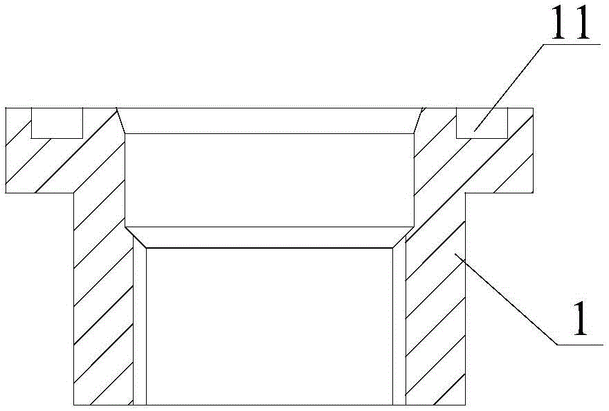
[0021] An improved oil cooler welded joint, its structure is as follows figure 1 As shown, it can be arranged on both sides of the oil cooler core 6 to connect the oil cooler core 6 and the water chamber 3, as shown in Figure 2-4 shown. The welded joint 1 is in plane contact with the inner side wall of the water chamber 3, and a sealing groove 11 is opened on the connection contact surface, and a sealing ring 12 is arranged in the sealing groove 11, thereby increasing the pressing area, and further making the pressing and sealing Correspondingly increased resistance, no product leakage will occur even under harsh working conditions, and can withstand high pressure.

[0022] The welded joint 1 is connected with the connecting pipe 5 by threads during application. A connecting pipe sealing ring 2 is also provided at the joint between the connecting pipe 5 and the welded joint 1 , and a combined sealing gasket 4 is provided at the contact surface between the connecting pipe 5 ...


PUM


Abstract

The invention relates to improved oil cooler welding joints arranged on the two sides of a core of an oil cooler to connect the core of the oil cooler with a water chamber. Each improved oil cooler welding joint is characterized in that sealing trenches are formed in the connection contact face of the welding joint and the water chamber, and sealing rings are arranged in the sealing trenches. Compared with the prior art, the improved oil cooler welding joints are applied in press fitting of the oil cooler and the water chamber, the pressing area can be increased, pressing airtightness is improved accordingly, product leakage cannot occur even when the working condition is severe, and the welding joints can bear higher pressure. In addition, threads for assembling welding joints are likely to be damaged and scrapped when the existing joints are assembled multiple times, and it is difficult to achieve the long-term normal working condition use purpose even though the existing joints are assembled; and due to the fact that the sealing rings are additionally arranged on each improved oil cooler welding joint, and after-sale services caused by leakage due to assembly are avoided.

Description

technical field [0001] The invention relates to a welding joint, in particular to an improved oil cooler welding joint. Background technique [0002] At present, many automotive radiators use built-in oil coolers to cool the transmission oil, especially the structure of the oil cooler parts and radiator water chamber assembly has certain defects, and there will be oil leakage during use. [0003] The welded joints of the oil cooler are welded together with the radiator plate, the radiator fin and the bottom plate to form an oil cooler. When the oil cooler is assembled with the water chamber, it depends on the plane seal. Oil coolers are generally made of aluminum or copper and stainless steel. The structure has control type or laminated type or plate type and so on. In addition to lubricating and cleaning the engine, the engine oil can also absorb the heat released by the engine, but the engine oil can only circulate in the sealed engine to release the absorbed heat slowl...

Claims


Application Information

Patent Timeline
IPC IPC(8): F28F9/26F28F11/00
Inventor 许继友
Owner SHANGHAI DELANG AUTO PARTS MFG
Learn More