Drying room afterheat recycling device

A technology of waste heat recovery device and heat exchange device, which is applied in drying, heat exchanger type, indirect heat exchanger, etc., can solve the problems of heat energy not being used effectively, failing to be recycled, heat energy loss, etc., To achieve the effect of simple structure, convenient device cleaning and maintenance, and recycling

Inactive Publication Date: 2016-03-02
JIANGSU HAIDA DYEING & PRINTING MACHINERY
View PDF4 Cites 1 Cited by
  • Summary
  • Abstract
  • Description
  • Claims
  • Application Information

AI Technical Summary

Problems solved by technology

Although this technology can achieve the effect of dehumidification, in the process of dehumidification, because the dehumidification air contains a lot of heat, it cannot be recycled, and a large amount of heat energy is lost in the air outside the equipment, resulting in a large waste of energy. It has not been effectively used, resulting in a large energy consumption in the drying room during the baking operation

Method used


Image

  • Drying room afterheat recycling device
  • Drying room afterheat recycling device
  • Drying room afterheat recycling device

Examples


Embodiment Construction

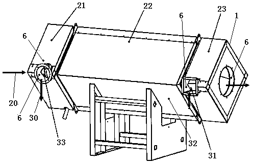
[0017] The present invention will be further described below in conjunction with the accompanying drawings. Such as Figure 1-3 A drying room waste heat recovery device shown includes a heat exchange body, which is characterized in that: the heat exchange body includes a shell 1 and a fresh air channel 3 and a hot exhaust gas channel 2 in the shell 1, and the fresh air channel 3 and the hot exhaust gas channel 2 are provided with a heat exchange device 4, which absorbs the heat of the exhaust gas flowing through the hot exhaust gas channel 2 by using the principle of heat exchange.

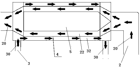
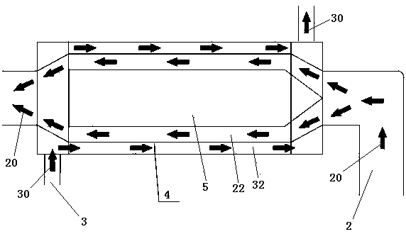
[0018] Further, the hot exhaust gas passage 2 sequentially includes a hot exhaust gas tank 21 , a heat exchange area 22 and a cooled exhaust gas tank 23 according to the hot exhaust gas flow direction 20 ; the fresh cold air flow direction 30 is opposite to the hot exhaust gas flow direction 20 .

[0019] Further, the hot exhaust gas channel 2 in the heat exchange area 22 is located at the center...


PUM


Abstract

The invention discloses a drying room afterheat recycling device. The device comprises a heat exchanging body, wherein the heat exchanging body comprises a shell, a fresh air passage and a hot waste air passage which are arranged inside the shell; a heat exchanging device is arranged between the fresh air passage and a hot waste air passage; the heat of waste air which flows through the hot waste air passage can be absorbed by utilizing a heat exchange theory. By utilizing a circulating heat conduction and exchange theory, the drying room afterheat recycling device disclosed by the invention is capable of realizing recycle of waste heat, energy-saving and environment-friendly; the drying room afterheat recycling device disclosed by the invention is of a square box type structure and is simple in structure, convenient to wash and maintain and small in floor space by being placed above a drying room; the temperature of a pipeline wall can be reduced by the waste air after the waste air passes through the afterheat recycling device; heat radiation caused by the temperature of a waste air exhausting system to the air can be reduced; the comprehensive energy conservation is about 20%.

Description

technical field [0001] The invention relates to the field of heat energy recovery devices, in particular to a drying room waste heat recovery device. Background technique [0002] At present, in the entire field of baking in the baking room, almost all baking equipment uses the low humidity and low temperature air outside the baking equipment to directly exchange the high humidity and high temperature moisture inside the equipment to bake the materials in the equipment. , Dehumidification. Although this technology can achieve the effect of dehumidification, in the process of dehumidification, because the dehumidification air contains a lot of heat, it cannot be recycled, and a large amount of heat energy is lost in the air outside the equipment, resulting in a large waste of energy. It has not been effectively utilized, resulting in a large energy consumption in the drying room during the baking operation. Contents of the invention [0003] Aiming at the deficiencies of ...

Claims


Application Information

Patent Timeline
Patent Type & Authority Applications(China)
IPC IPC(8): F26B25/00F28D7/10
CPCF26B25/005F28D7/10Y02P70/10
Inventor 吴建忠陈丽洁周伟红许晓晓张晨欣张伟黄志远邹学峰章沉哮
Owner JIANGSU HAIDA DYEING & PRINTING MACHINERY
Why Eureka
Try Eureka