
Analysis method for steady-state security region of electric-pneumatic interconnected integrated energy system

An integrated energy system and static security domain technology, which is applied in the static security domain analysis field of an integrated energy system of electricity-gas interconnection, can solve problems such as difficulty in reflecting the security constraints of natural gas networks and over-optimistic static security domain results.

Active Publication Date: 2016-02-24
HOHAI UNIV
View PDF5 Cites 31 Cited by
  • Summary
  • Abstract
  • Description
  • Claims
  • Application Information

AI Technical Summary

Problems solved by technology

[0005] Purpose of the invention: The technical problem to be solved by the present invention is to solve the problem that the static security domain of the existing power system is difficult to reflect the security constraints of the natural gas network, that is, the result of the static security domain of the power system is too optimistic

Method used


Image

  • Analysis method for steady-state security region of electric-pneumatic interconnected integrated energy system
  • Analysis method for steady-state security region of electric-pneumatic interconnected integrated energy system
  • Analysis method for steady-state security region of electric-pneumatic interconnected integrated energy system

Examples


Embodiment Construction

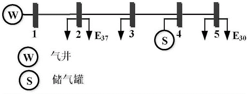
[0059] Attached below Figure 1~5 Explain in detail the technical process of the invention:

[0060] Establishing a steady-state energy flow model of an electric-gas interconnected integrated energy system

[0061] Establish a steady-state energy flow model of the power system:

[0062] Assume that the power system contains n e +1 node, b e lines; define node 0 as a balanced node, G={1,2,L,n eg} is the PV node, L={n eg +1,n eg +2,L,n e} is the PQ node, B e for the line set.

[0063] For branch l connecting nodes i and j, its branch power can be expressed as:

[0064] P l = ( g i j + g ...


PUM


Abstract

The invention discloses an analysis method for a steady-state security region of an electric-pneumatic interconnected integrated energy system. The method comprises the following steps: firstly, building a steady-state energy flow model of the electric-pneumatic interconnected integrated energy system; secondly, proposing the concept of the steady-state security region of the electric-pneumatic interconnected integrated energy system by referring to a definition and a model of the steady-state security region of a power system; thirdly, obtaining a group of boundary operation points on the boundary of the security region through repeated energy flow calculation; and finally, obtaining the steady-state security region of the electric-pneumatic interconnected integrated energy system on the basis of linear hyperplane fitting. The security region model disclosed by the invention provides a theoretical basis for real-time operation scheduling and online security evaluation of the electric-pneumatic interconnected integrated energy system.

Description

technical field [0001] The invention relates to a method for analyzing a static security domain of an electric-gas interconnected integrated energy system, belonging to the technical field of online security analysis and evaluation of an integrated energy system. Background technique [0002] Compared with thermal power units, gas turbine units have less carbon emissions, faster dynamic response, and shorter construction period. Therefore, the proportion of gas turbine power generation has gradually increased in recent years. Correspondingly, the coupling between the power system and the natural gas system is also increasing. On the other hand, the advantages of power-to-gas technology in large-scale energy storage are expected to realize the two-way flow of energy flow between the power grid and the gas grid. The coupling and interconnection of the power system and the natural gas system is expected to promote the large-scale grid connection of new energy from two aspects:...

Claims


Application Information

Patent Timeline
Patent Type & Authority Applications(China)
IPC IPC(8): H02J3/00G06F19/00G06Q50/06
CPCG06Q50/06H02J3/00H02J2203/20
Inventor 卫志农陈胜孙国强孙永辉臧海祥朱瑛陈霜张思德
Owner HOHAI UNIV
Learn More