
Tension force applying device for steel wire with small diameter

A technology of applying device and steel wire, which is applied in the direction of measuring device, applying stable tension/pressure to test the strength of materials, instruments, etc., can solve the problems of cumbersome operation and expensive equipment

Inactive Publication Date: 2016-02-24
ZHEJIANG JIAOKE TRAFFIC TECH CO LTD
View PDF8 Cites 8 Cited by
  • Summary
  • Abstract
  • Description
  • Claims
  • Application Information

AI Technical Summary

Problems solved by technology

The jack tensioning method uses electrified equipment, which is easy to control the tension, but the equipment is expensive and the operation is cumbersome

Method used


Image

  • Tension force applying device for steel wire with small diameter
  • Tension force applying device for steel wire with small diameter
  • Tension force applying device for steel wire with small diameter

Examples


Embodiment Construction

[0020] The technical solution of the present invention will be described in further detail below in conjunction with the accompanying drawings and embodiments.

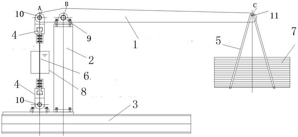
[0021] Such as figure 2 As shown, the present invention discloses a small-diameter steel wire tensioning force application device based on the principle of leverage. The device as a whole is a self-balancing lever, including a base 3, a column 2, a lever 1, a standard counterweight 7, a pair of clamps 4, Corrosive solution container 8, the pair of clamps 4 are composed of upper clamps and lower clamps;

[0022] The bottom end of the column 2 is fixed on the base 3;

[0023] Described lever 1 is in the direction of its arm length, at point B, moves by rotating shaft frame 9 and is limited to the top of column 2, and at point C, a standard counterweight 7 is suspended by counterweight frame 5, and at point A The upper clamp is hinged by the rotating shaft 10, and the horizontal length between BC is greater than the h...


PUM


Abstract

A tension force applying device for a steel wire with a small diameter is disclosed, is used for applying and maintaining tension force to a steel wire with a small diameter, and is particularly used for steel wire corrosion tests under tension states. The device is a balanced lever from the whole, and is free of an external fixing gear. Two ends of the steel wire are fixed to the device through specially prepared clamps, and then tension force is applied to the steel wire through a counterweight. The force with a specific value can be applied to the steel wire simply and conveniently and can be maintained permanently, and no energy is consumed in the maintaining period, thus achieving low carbon and environmental protection.

Description

technical field [0001] The device of the invention is applied to the application and maintenance of the tension force of the small-diameter steel wire, and is specifically applied to the corrosion test of the steel wire under a stress state. Background technique [0002] At present, the main method used in the application of steel bar and steel strand tension is the jack tension method. The jack tensioning method described, such as figure 1 As shown, the main components include a pedestal, a loading jack, a load sensor, a clamp at the tension end, and a clamp at the fixed end. Its operating principle is as follows: steel bars or steel strands are anchored on the pedestal through tension end fixtures and fixed end fixtures, and then tensioned with a jack, and the precise force value is controlled by the load sensor. The loading jack is a complete set of hydraulic system (specifically including jack, oil pipe, oil pump, etc.), and the load sensor is a set of measuring device...

Claims


Application Information

Patent Timeline
Patent Type & Authority Applications(China)
IPC IPC(8): G01N3/14G01N17/00
CPCG01N3/14G01N17/006
Inventor 田浩晁春峰徐建胡美张勇
Owner ZHEJIANG JIAOKE TRAFFIC TECH CO LTD
Learn More