
A fully automatic screw locking machine

A screw-locking machine, fully automatic technology, applied in the direction of metal processing, metal processing equipment, manufacturing tools, etc., can solve the problems of poor coherence, low efficiency, slow progress, etc., to achieve strong continuity of continuous work, convenient use and management , a strong coherent effect

Active Publication Date: 2018-07-06
ZHEJIANG OUGE AUTOMATION TECH CO LTD
View PDF8 Cites 0 Cited by
  • Summary
  • Abstract
  • Description
  • Claims
  • Application Information

AI Technical Summary

Problems solved by technology

[0003] The working efficiency of this automatic screw locking machine is not high, and it mainly has the defects in the following aspects: (1) The product is to place multiple pieces at one time, and then wait for them to finish locking the screws together, then take them off, and then install the next batch , so there is a break in the middle, the coherence is not strong, and the efficiency is low
[0004] (2) Only a limited number of automatic screwdrivers can be placed on it. The horizontal and vertical cross transport frames are used to shift and drive screws. The screw holes on each product must be locked one by one. This progress is slow and the efficiency is very low.
[0005] (3) The screw storage box cannot automatically sort the screws, and it cannot prepare the pre-order action of locking the screws well, that is, the screw head faces down and the nut faces up, and then there is a whole row of preparatory screws waiting for this state, and it can be continuously locked. permutation supply, so the patented technology is backward and inefficient
[0006] (4) The products with locked screws cannot be stripped continuously. It is necessary to wait until all the products placed on them in the same batch have been screwed before they can be stripped uniformly, which is inefficient.

Method used


Image

  • A fully automatic screw locking machine
  • A fully automatic screw locking machine
  • A fully automatic screw locking machine

Examples


Embodiment

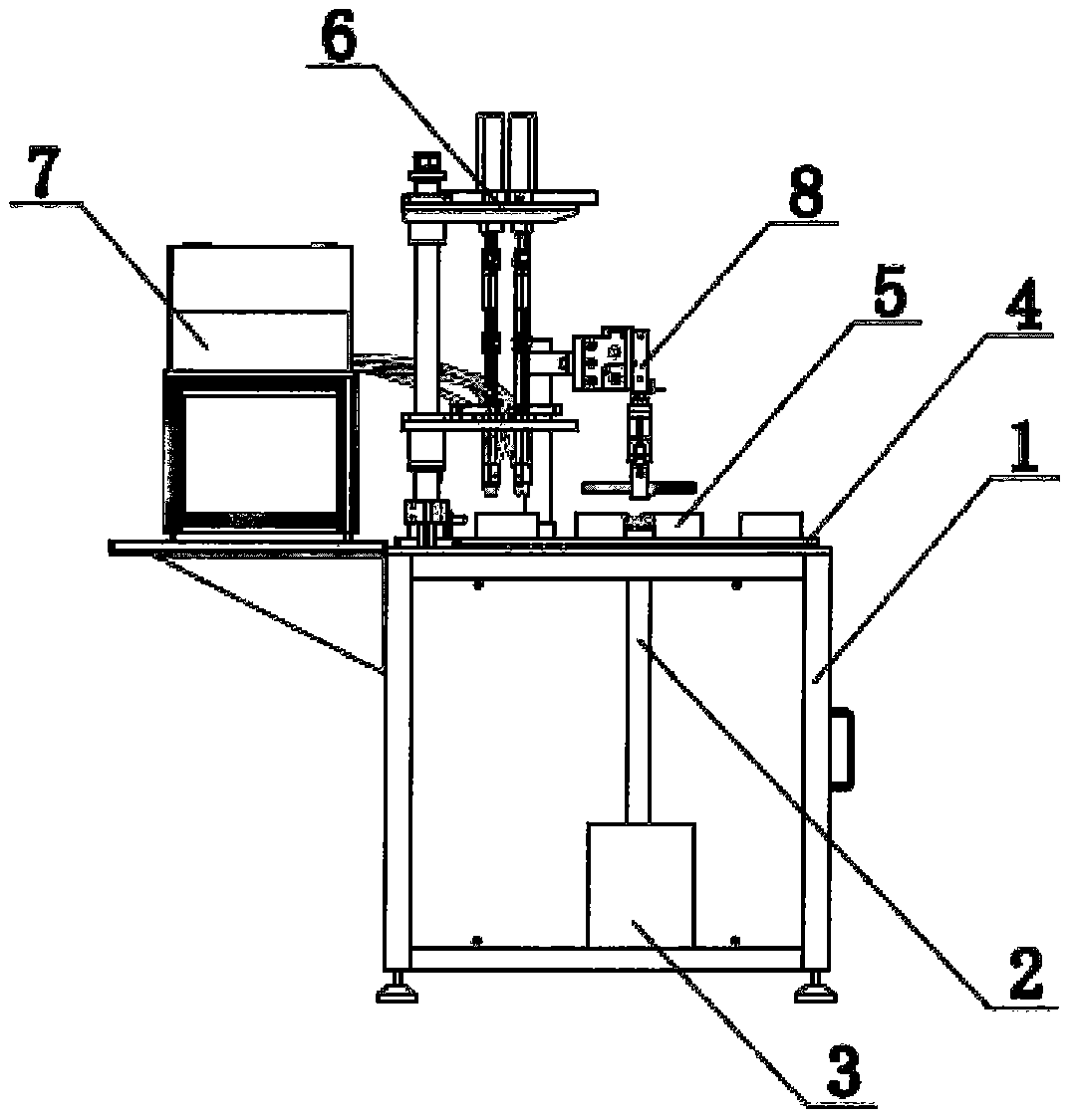
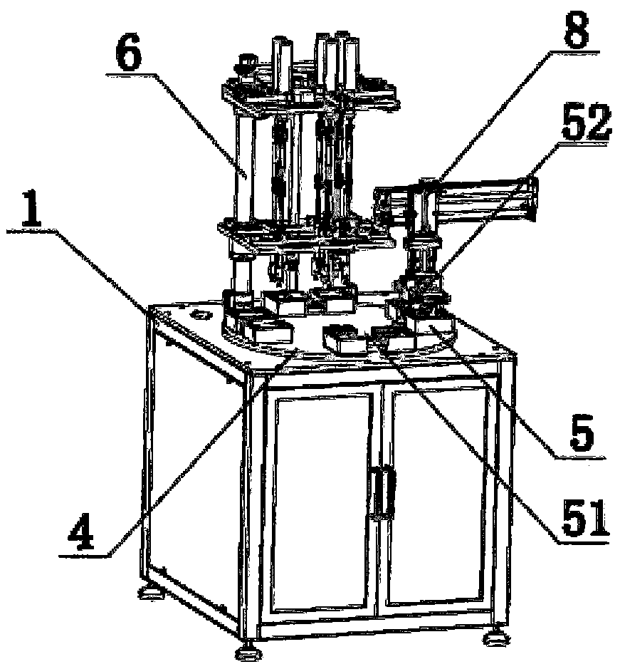
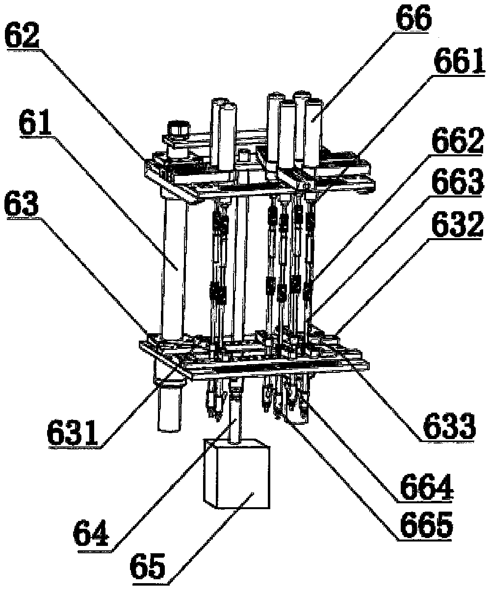
[0029] Example: such as figure 1 with 2 As shown, a fully automatic screw locking machine includes a frame 1, a main shaft 2 is vertically arranged in the middle of the frame 1, the lower end of the main shaft 2 is accommodated in the frame 1 and connected with a main motor 3, and the upper end of the main shaft 2 extends Out of the frame 1 and connected to a turntable 4, the main shaft 2 is just connected to the bottom of the center of the turntable 4, and a circle of four mold boxes 5 is arranged around the center of the turntable 4, and these mold boxes 5 are arranged at equal arc lengths. , the radius of each mold box 5 from the center of the turntable 4 is equal, that is, the pattern layout is consistent, so as to ensure that each mold box 5 always moves away from the position when the previous mold box 5 moves away from the position during the step-by-step rotation of the turntable 4 The state of placement is consistent, and the exposed surface of the upper end of each ...


PUM


Abstract

The invention discloses a fully-automatic screw locking machine which comprises a rack. The fully-automatic screw locking machine is characterized in that the middle part of the rack is vertically provided with a main shaft; the lower end of the main shaft is taken into the rack and is connected with a primary motor; the upper end of the main shaft extends out of the rack and is connected with a rotary plate; the main shaft is just connected with the bottom of the center of the rotary plate; a plurality of mould boxes with equal-arc-length spacing among one another, which surround the center of the rotary plate, are arranged on a loop line on the rotary plate; an automatic screw locking assembly is arranged on a position, above one mould box, at the side of the rotary plate; the automatic screw locking assembly is connected with an automatic screw supply assembly; and the side of the rotary plate is provided with an automatic product removing assembly, which is arranged at a next-step inlet position of the automatic screw locking assembly, in a rotary direction of the rotary plate. The fully-automatic screw locking machine is not great in integral dimension, small in floor space, convenient to use and control, high in continuous working consistency, and high in efficiency and precision in work.

Description

technical field [0001] The invention relates to the technical field of screw locking machines, in particular to a fully automatic screw locking machine. Background technique [0002] Automatic locking screw machine, such as the automatic locking screw machine described in the patent application 201410499905.8, includes: worktable, displacement device, screw locking device and screw storage box, the displacement device is set on the workbench, and the screw locking device is slidingly set In the displacement device, the screw storage box is set on the workbench, and is close to the displacement device and the screw locking device. The above-mentioned automatic locking screw machine controls the screw locking device by setting the first Y-axis guide rail, the first Y-axis drive member, the first X-axis guide rail, the first motor, the first slider and the first telescopic cylinder as a displacement control unit. An electric batch, the second Y-axis guide rail, the second Y-ax...

Claims


Application Information

Patent Timeline
Patent Type & Authority Patents(China)
IPC IPC(8): B23P19/06
CPCB23P19/002B23P19/069
Inventor 刘静生
Owner ZHEJIANG OUGE AUTOMATION TECH CO LTD
Learn More