
Mechanism for driving core pulling of inclined mold core through sliding block

An oblique core-pulling and slider technology, which is applied in the field of core-pulling mechanisms, can solve problems such as large product size errors, increased mold costs, and high injection pressure.

Inactive Publication Date: 2017-05-10
牟维军
View PDF0 Cites 3 Cited by
  • Summary
  • Abstract
  • Description
  • Claims
  • Application Information

AI Technical Summary

Problems solved by technology

At present, in the mold manufacturing industry, the rack and pinion core pulling mechanism is usually used. Although this mechanism can meet the production requirements of this type of product, the rack and pinion core pulling mechanism has the following defects: 1. It requires multi-stage gears and gears. Cooperate with the hydraulic cylinder to realize oblique core pulling, resulting in many parts, difficult assembly, and poor stability of mechanism transmission
2. The multi-stage gear rotation mechanism is huge, and there are many mold parts, which will increase the overall size of the mold. Due to the increase in the overall size of the mold, when selecting molding equipment, it is necessary to choose an injection machine or a die-casting machine with high injection pressure. It will cause the cost of the mold itself and the cost of product processing to increase
3. Due to the use of multi-stage rotating mechanism, the size error of the product is large, and once the mold is damaged, it will take a long time to repair

Method used


Image

  • Mechanism for driving core pulling of inclined mold core through sliding block
  • Mechanism for driving core pulling of inclined mold core through sliding block
  • Mechanism for driving core pulling of inclined mold core through sliding block

Examples


Embodiment Construction

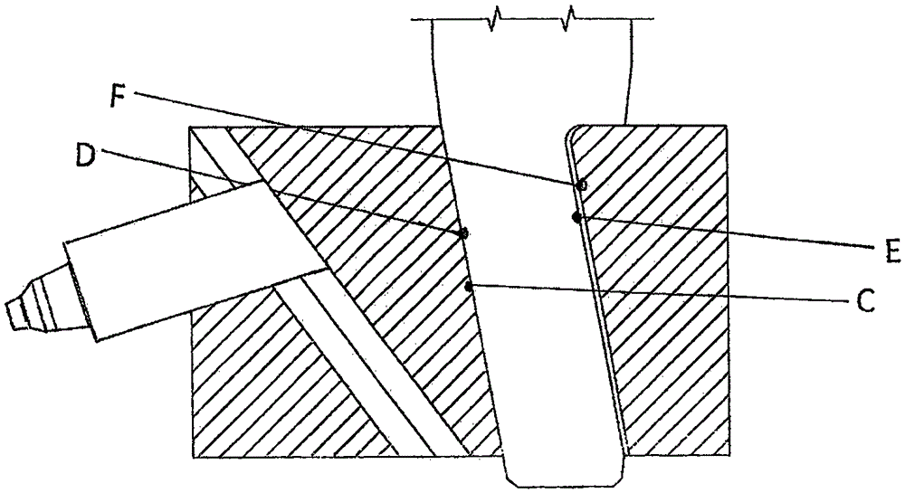
[0022] As shown in the figure, it is a mechanism that uses the slider to drive the oblique core to pull the core. Its specific implementation is as follows. (375), movable template (175), first wear block (575), second wear block (675), first screw (35), second screw (25), fixed template (775), the The two sides of the slider (475) are provided with T-shaped bosses, the center of the slider (475) is provided with a square oblique through hole, and the left side of the slider (475) is provided with an inclined surface. T-shaped groove, the slide block (475) is installed in the concave T-shaped groove provided on the moving template (175), and the forming slide block ( 55), the right side of the forming slide block (55) is provided with concave-convex T-shaped grooves, and the set concave-convex T-shaped grooves cooperate with the concave T-shaped grooves on the inclined surface of the slide block (475) to form a sliding gap, and the forming slide block ( 55) is fastened to the...


PUM


Abstract

The invention relates to a mechanism for driving core pulling of an inclined mold core through a sliding block. The mechanism is formed by the sliding block (475), a dog-leg cam (375), a molding sliding block (55) and a molding mold core (275); T-shaped bosses are arranged on the two side faces of the sliding block (475), a square inclined through hole is formed in the center of the sliding block (475), a slope is arranged on the left side of the sliding block (475), a T-shaped groove is formed in the arranged slope, the sliding block (475) is installed in a concave T-shaped groove formed in a movable mold plate (175), the molding sliding block (55) is installed in the concave T-shaped groove formed in the left side of the sliding block (475), a concave-convex T-shaped groove is formed in the right side of the molding sliding block (55) and is in slide clearance fit with the concave T-shaped groove in the slope of the sliding block (475), and the molding mold core (275) is connected to the left side of the molding sliding block (55) in a fastening manner.

Description

technical field [0001] The invention relates to a core-pulling mechanism of a metal die-casting mold and a plastic injection mold, which utilizes a slide block to drive an oblique core-pulling mechanism. Background technique [0002] In the process of product design and manufacturing, there will be oblique concave or oblique long holes. Since the oblique concave or oblique long holes are different from the mold opening direction, or vertical or at a certain angle, the product cannot be demoulded directly at this time, so in In the design of the mold structure, the parts with oblique concave or oblique long holes must be designed to be movable. Before the product is demoulded, the oblique core must be pulled out before the product can be demoulded, and the core is pulled out and reset. The mechanism is called the oblique core-pulling mechanism. At present, in the mold manufacturing industry, the rack and pinion core pulling mechanism is usually used. Although this mechanism ...

Claims


Application Information

Patent Timeline
IPC IPC(8): B22D17/22B29C45/33
CPCB22D17/22B29C45/33
Inventor 牟维军
Owner 牟维军
Learn More