
Especially mobile working machine and manufacturing method for vehicle concrete pump

A technology of concrete pump and working machine, applied in the field of concrete distribution rod, hinge point of support leg, and vehicle concrete pump, can solve the problems of limited stroke and inaccuracy of tools, and achieve the effect of saving materials

Active Publication Date: 2017-09-12
PUTZMEISTER ENG GMBH
View PDF6 Cites 0 Cited by
  • Summary
  • Abstract
  • Description
  • Claims
  • Application Information

AI Technical Summary

Problems solved by technology

However, such a process implies rotating the rod base by 180°, since the machining center is very limited in its tool travel, and therefore the travel is not sufficient to form the hole from above or below
Rotating the rod base in turn implies correspondingly elaborate and expensive equipment for fixing the parts, or inaccuracies caused by the drilling itself when forming the holes
However, the hinge pin can only be positioned very close to the load-bearing structure of the rod base if the machining tool is moved in the inner region between the link plates of the rod base and from there machines at least one of the two bearing holes thus still retaining sufficient space for processing instruments

Method used


Image

  • Especially mobile working machine and manufacturing method for vehicle concrete pump
  • Especially mobile working machine and manufacturing method for vehicle concrete pump
  • Especially mobile working machine and manufacturing method for vehicle concrete pump

Examples


Embodiment Construction

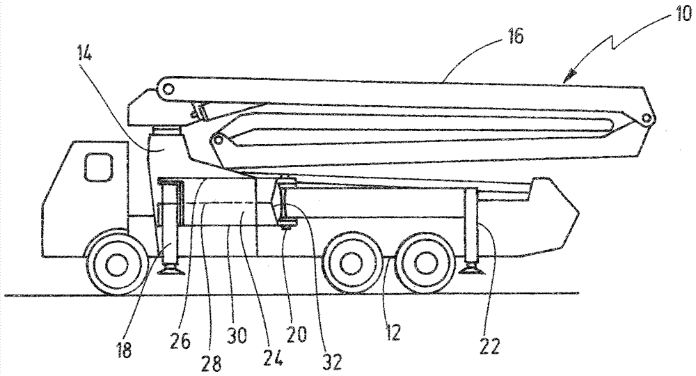
[0021] figure 1 The vehicle concrete pump 10 represented in includes a chassis 12, a load-bearing structure 14 mounted on the chassis and fixed to the vehicle, a concrete distribution rod 16 mounted on the load-bearing structure so as to be rotatable around a vertical axis of rotation, and two supports or rotating Legs 22 are each hinged to the load-bearing structure 14 via hinge points 20 and can be swiveled out about a vertical axis of rotation. The support legs 18, 20 can be moved out of the travel position shown into a support position further from the longitudinal axis of the vehicle.

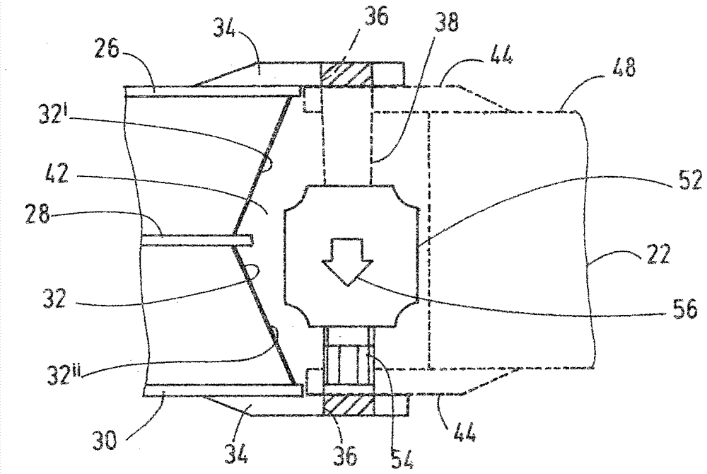
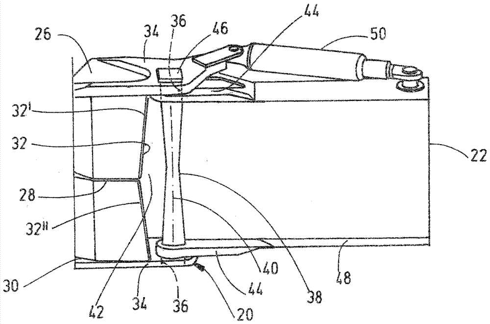
[0022] Each hinge point 20 is arranged at a box-type structure 24 consisting of three flanges 26, 28, 30 and wall panels welded thereto. In this case, the boundary wall 32 facing the hinge point 20 has a triangular hollow profile.

[0023] like figure 2 As best shown, the hinge points 20 each have two bearing plates 34 which are welded to the flanges 26 , 30 and which protrude above th...


PUM


Abstract

The invention relates to a vehicle-mounted concrete pump (10) comprising a vehicle-mounted support structure (14) for a concrete distribution rod (16) and at least two pivotally mounted via articulated joints (20). Support jacks (22) connected to the support structure (14), each articulated joint (20) comprising two support plates (34) made of solid material, each support plate having a bearing hole (36) and in the support structure The delimiting wall ( 32 ) of ( 14 ) protrudes at a lateral distance from each other in the form of bifurcations above the edge and has hinged bolts ( 38 ) traversing the bearing holes ( 36 ). According to the invention, the central area between the support plates (34) of the delimiting wall (32) facing the hinge bolt (38) is at a distance from the hinge bolt (38) compared to its edge area adjacent to the support plate (34). Axis (40) is farther.

Description

technical field [0001] The invention relates to a mobile working machine, in particular a vehicle-mounted concrete pump, having: a load-bearing structure secured to the vehicle, in particular for a concrete distribution bar; and at least two supports hinged to the load-bearing structure via respective hinge points a leg, wherein each hinge point comprises two support plates made of solid material, each support plate provided with a bearing hole and protruding at a lateral distance from each other in a bifurcated manner above the edge of the demarcation wall of the load-bearing structure, and A hinge pin extends vertically through the mutually aligned bearing holes. The invention also relates to a method for manufacturing a hinge point for a support leg of such a mobile working machine. Background technique [0002] The hinged coupling of the swivel leg to the rod base of the vehicle concrete pump is similar in its construction to the two links of a bicycle chain interconnec...

Claims


Application Information

Patent Timeline
Patent Type & Authority Patents(China)
IPC IPC(8): B66C23/80E04G21/04
CPCB66C23/80E04G21/0436E04G21/0445B60S9/02F16C11/04
Inventor D.法伊格尔K.韦斯特曼
Owner PUTZMEISTER ENG GMBH
Learn More