Breaker
What is Al technical title?
Al technical title is built by PatSnap Al team. It summarizes the technical point description of the patent document.
A circuit breaker, on-off technology, applied to circuits, parts of protection switches, electrical components, etc., can solve problems such as inconvenient installation and maintenance, achieve convenient maintenance, avoid killing and damage, and improve work efficiency.
Inactive Publication Date: 2016-02-17
泰兴市华诚机电制造有限公司
View PDF5 Cites 0 Cited by
Summary
Abstract
Description
Claims
Application Information
AI Technical Summary
This helps you quickly interpret patents by identifying the three key elements:
Problems solved by technology
Method used
Benefits of technology
Problems solved by technology
[0003] At present, in the high-voltage circuit breakers widely used in coal mine power systems, their functional components, such as operating mechanisms, motors, and releases, are installed in the narrow space of the circuit breaker box. With the gradual miniaturization of equipment requirements, , very inconvenient to install and maintain
Method used
Image
Click on the blue label to locate the original text in one second.
Reading with bidirectional positioning of images and text.
Examples
Embodiment Construction
[0029] The present invention will be further described below in conjunction with drawings and embodiments.
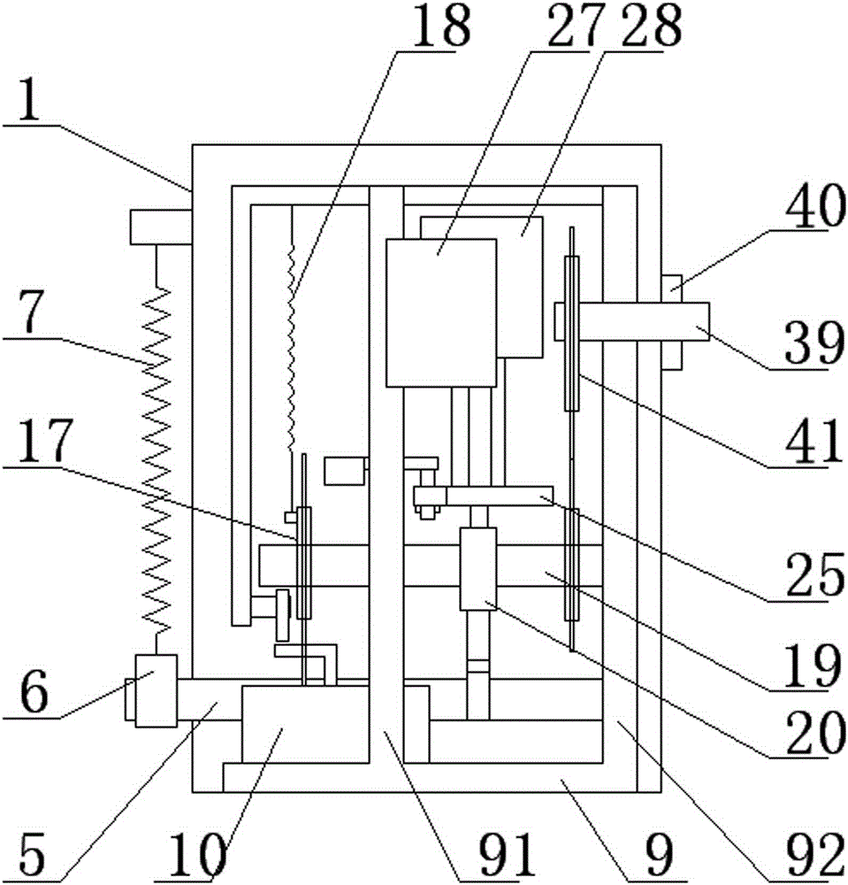
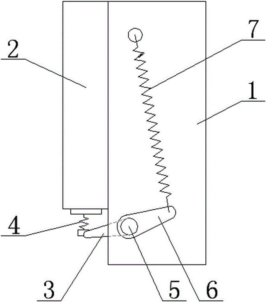
[0030] Figure 1-4As shown, a modular circuit breaker includes an insulating cabinet 1, a vacuum tube 2, an on-off toggle arm 3, an overtravel spring 4, a main shaft 5, an opening toggle arm 6, an opening tension spring 7, a closing toggle arm 8, and a mechanism Bottom plate 9, mechanism left and right vertical plates 91, 92, motor 10, input shaft 11, driving half clutch 12, clutch spring 13, driven half clutch 14, clutch lever 15, auxiliary switch 16, sprocket group 17, closing Tension spring 18, closing shaft 19, cam 20, closing plate 21, driving plate 22, sector plate 23, return spring 24, tripping plate 25, roller groove 26, electric tripping device 27, undervoltage tripping Device 28, undervoltage spring 29, gate opening plate 30, gate opening lever 31, gate opening reset spring 32, check lever 33, check adjustment screw 34, display pull rod 35, display lever 36, ...
PUM
Abstract
The invention relates to a breaker. The breaker comprises an insulation cabinet, a main shaft, an on-off connecting lever, a closing connecting lever, an operating mechanism, an opening connecting lever and an opening extension spring, wherein the main shaft is connected with the insulation cabinet through a penetrating mode, the on-off connecting lever, the closing lever and the opening lever are fixed on the main shaft in a penetrated mode, the on-off connecting lever is connected with a vacuum tube via a super-path spring, the opening connecting lever is connected with the insulation cabinet via the opening extension spring, and the operating mechanism is slidably supported in the insulation cabinet by a mechanism base plate such that, when inserted into the insulation cabinet, the operating mechanism engages the closing connecting lever to be in driving cooperation therewith, and when pulled out of the insulation cabinet, the operating mechanism disengages from the driving cooperation with the closing connecting lever; and the operating mechanism comprises a motor, an input shaft, a closing shaft, a closing cam and a closing connecting rod set, wherein the motor is installed on the mechanism base plate, the input shaft and the closing shaft pass through vertical plates at both sides of the mechanism base plate, the motor drives the input shaft, the input shaft drives the closing shaft via a sprocket wheel set, and the closing shaft drives the closing shaft connecting rod set via the closing cam so as to drive the closing connecting lever to rotate the main shaft to enter a closing state.
Description
[0001] This application is a divisional application with the patent title: "A Modular Circuit Breaker". The application date of the original application is 2014-7-17, and the application number is 201410339587.9. technical field [0002] The invention relates to a circuit breaker, in particular to a modular assembly and disassembly circuit breaker. Background technique [0003] At present, in the high-voltage circuit breakers widely used in coal mine power systems, their functional components, such as operating mechanisms, motors, and releases, are installed in the narrow space of the circuit breaker box. With the gradual miniaturization of equipment requirements, , It is very inconvenient to install and maintain. Contents of the invention [0004] Aiming at the fact that the circuit breaker in the prior art cannot meet the miniaturization and convenient installation and maintenance requirements, the present invention provides a modular circuit breaker with simple and comp...
Claims
Application Information
Patent Timeline
Application Date:The date an application was filed.
Publication Date:The date a patent or application was officially published.
First Publication Date:The earliest publication date of a patent with the same application number.
Issue Date:Publication date of the patent grant document.
PCT Entry Date:The Entry date of PCT National Phase.
Estimated Expiry Date:The statutory expiry date of a patent right according to the Patent Law, and it is the longest term of protection that the patent right can achieve without the termination of the patent right due to other reasons(Term extension factor has been taken into account ).
Invalid Date:Actual expiry date is based on effective date or publication date of legal transaction data of invalid patent.