
A test method for double-drive electric spindle

A test method, the technology of the electric spindle, applied in the testing of mechanical components, testing of machine/structural components, measuring devices, etc., can solve the problems of reducing the accuracy of results, affecting magnets, and increasing the centrifugal force of bearings, etc., and achieves wide versatility , the effect of simple structure

Inactive Publication Date: 2018-01-23
ANYANG INST OF TECH
View PDF7 Cites 0 Cited by
  • Summary
  • Abstract
  • Description
  • Claims
  • Application Information

AI Technical Summary

Problems solved by technology

During this measurement process, the vibration of the spindle unit will inevitably affect the adsorption state of the magnet, which will affect the measurement results of the vibration state of the spindle unit and reduce the accuracy of the results
[0007] The impact of the speed on the spindle unit is also prominent. When the speed gradually increases, the heat generated will inevitably increase, and the centrifugal force on the bearing will increase, and the inertial slip will also increase, which will affect the dynamic balance of the spindle unit.
[0008] However, the test bench and experimental method for the dual-drive electric spindle are still blank in China, and the relevant literature has not been reported.

Method used


Image

  • A test method for double-drive electric spindle
  • A test method for double-drive electric spindle
  • A test method for double-drive electric spindle

Examples


Embodiment Construction

[0032] The specific implementation manners of the present invention will be described in further detail below in conjunction with the accompanying drawings.

[0033] About the test device:

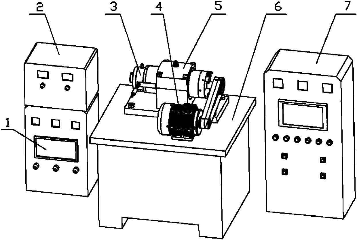
[0034] combine figure 1 and Figure 4 The test device of the present invention includes a main body base 6, a spindle unit 3, a positioning fixture 5, a drive motor 4, a synchronous belt 4.2, a synchronous pulley 4.1 4.3, a lubrication system 2, a cooling system 1, and a test head assembly, wherein the positioning fixture 3 passes through a bolt Fixed on the rear end of the main body base 6, the driving motor 4 is fixed on the front end of the main body base 6 by bolts.

[0035] combine figure 1 and image 3 , Figure 4 The main shaft unit includes a water inlet 3.3; an oil inlet 3.4; a water outlet 3.5; an internal motor 3.7; a front cover 3.6; a clutch 3.8.

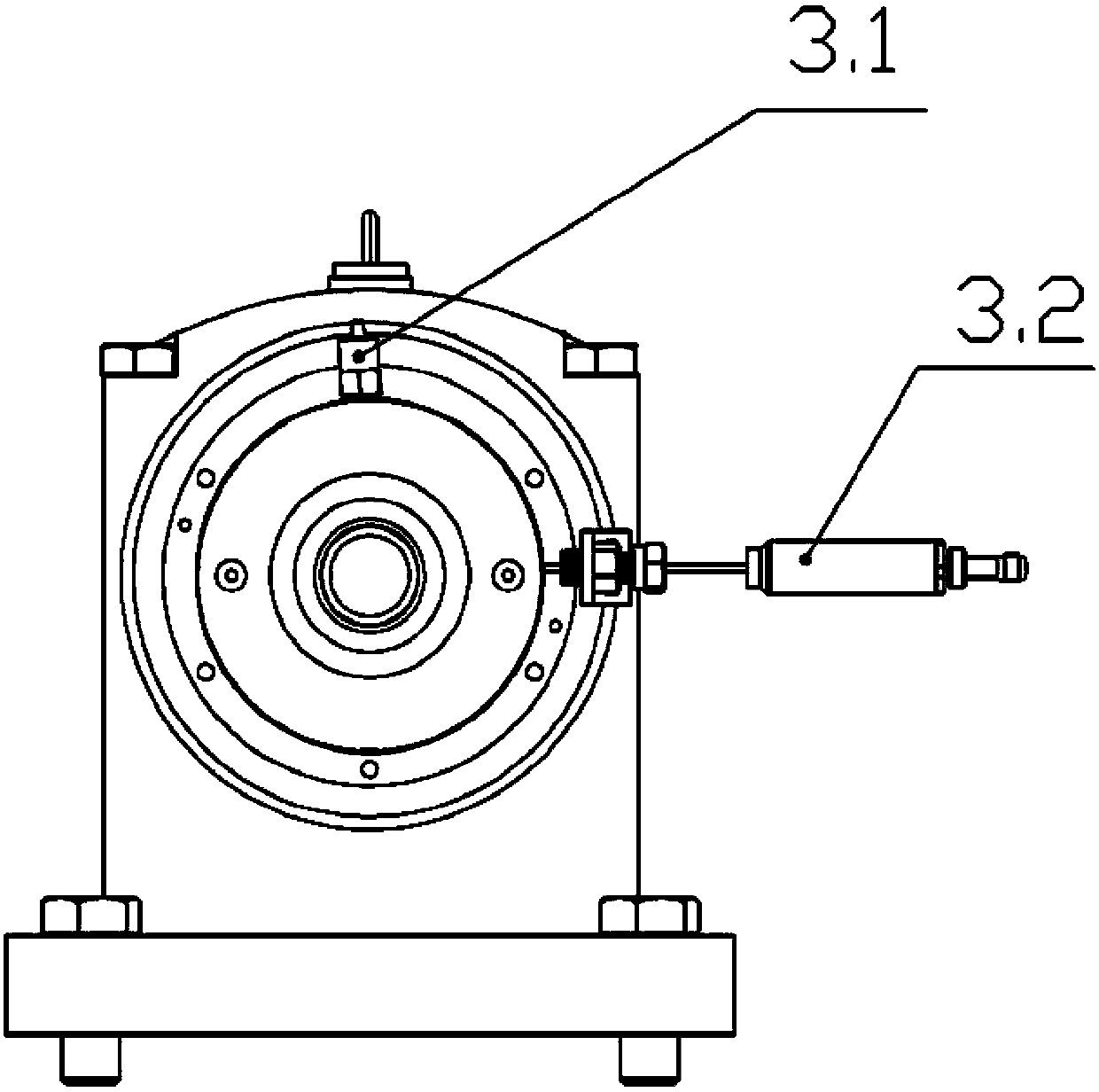
[0036] combine figure 2 The test head assembly includes a temperature sensor 3.2, a vibration sensor, a temperature measur...


PUM


Abstract

The invention provides a dual-drive spindle test stand and test method avoiding previous measurement defects, and aims at measuring temperature and vibration of a dual-drive spindle. The scheme is that the dual-drive spindle test stand comprises a computer, a frequency converter, a main body base, a spindle unit which is connected with the frequency converter, a positioning clamp, a driving motor which is connected with the frequency converter, a synchronous belt, synchronous belt wheels, a lubricating system, a cooling system and a test head component. The spindle unit is fixed on the upper end of the main body base via the positioning clamp. The driving motor is fixed on the main body base arranged at one side of the spindle unit. The driving motor and the spindle unit are connected via the synchronous belt wheels and the synchronous belt. The cooling system is connected with the water inlet and the water outlet of the spindle unit. The lubricating system is connected with the oil inlet of the spindle unit. The test head comprises a vibration measurement block which is arranged on the front large cover of the spindle unit, a vibration sensor of which the data acquisition end is connected with the vibration measurement block, and a temperature sensor which is installed in a temperature measurement hole.

Description

technical field [0001] The invention relates to the technical field of spindle unit tests, and mainly relates to a double-drive spindle test bench and a test method. Background technique [0002] Spindle units usually have motorized spindles and belt shafts, both of which have their own advantages and disadvantages. The electric spindle has a high speed and small torque; the belt shaft has a small speed and a large torque compared with the electric spindle; this will inevitably lead to different application occasions of the two. With the development of the spindle unit, in order to meet the requirements of the industry, the dual-drive spindle came into being. However, whether the comprehensive performance of this type of spindle unit meets the national and industry standards remains to be further studied. Among them, the main factors affecting the practical performance of the electric spindle are temperature, vibration and speed. [0003] Spindle units are generally used ...

Claims


Application Information

Patent Timeline
Patent Type & Authority Patents(China)
IPC IPC(8): G01M13/00
CPCG01M13/00
Inventor 何强李安玲张国烨张朋龙吕海周莫理超赵永博裴伟林
Owner ANYANG INST OF TECH
Learn More