Combined hot air continuous drying equipment

A drying equipment and combined technology, which is applied in the field of combined hot air continuous drying equipment, can solve the problems of hot air intensity reduction, maintenance, and drying effect decline, and achieve the effect of reasonable structure design and controllable strength

Inactive Publication Date: 2017-09-05
NINGXIA FATUFA VEGETABLE IND GRP CO LTD
View PDF7 Cites 0 Cited by
  • Summary
  • Abstract
  • Description
  • Claims
  • Application Information

AI Technical Summary

Problems solved by technology

[0003] However, the continuous dryer in the prior art has an air inlet below the feeding end of the screen, and the hot air blown by the hot blast stove is blown into the hot air drying chamber from the air inlet, and then blows out the vegetable material from the bottom of the screen. Drying, because the length of the hot air drying chamber is very long, even turning, the temperature of the hot air near the air inlet is very high and the intensity is very high, and as the distance from the air inlet increases, the temperature of the hot air drops sharply and the intensity also decreases. If you want to keep the temperature and intensity of the hot air unchanged, even the temperature and intensity can be adjusted artificially, even if you continue to increase the power of the hot air, such as the power of the motor, because the hot air dries The structural design defect of the drying room, as the length increases, the temperature and intensity of the hot air cannot be kept constant, and it is impossible to adjust the temperature and intensity, and it is difficult to maintain the temperature and intensity of drying for a long distance

Method used


Image

  • Combined hot air continuous drying equipment
  • Combined hot air continuous drying equipment
  • Combined hot air continuous drying equipment

Examples


Embodiment Construction

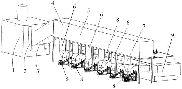
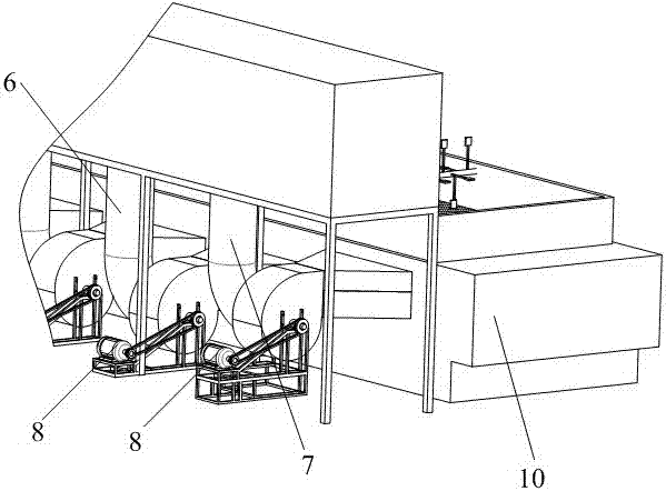
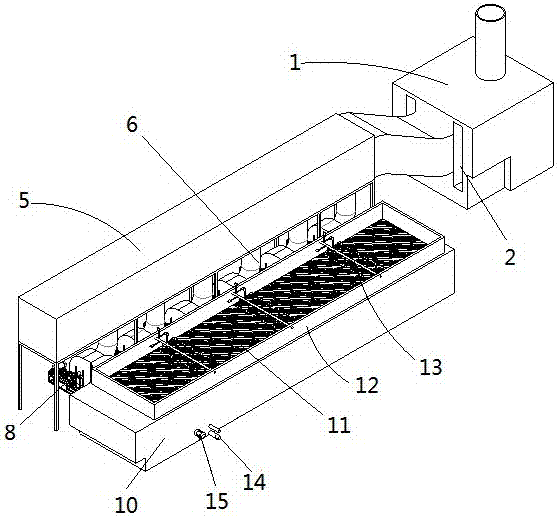
[0011] see Figure 1 to Figure 3 , the combined hot air continuous drying equipment includes a hot blast stove 1, an air distribution chamber 4, and a continuous dryer 9. The hot blast stove 1 is connected with the air distribution chamber 4, and the air distribution chamber 4 is connected with the continuous dryer 9. The hot blast stove 1 includes The natural air inlet 2 and the hot air outlet 3, the hot air outlet 3 of the hot blast stove 1 is connected to the air distribution chamber 4, and the air distribution chamber 4 includes an assembly air chamber 5 and at least three branch air ducts 6 connected to the assembly air chamber 5. The air chamber 5 is a sealed ventilation duct, one end of the ventilation duct is an air inlet, the air inlet is sealed with the hot air outlet 3 of the hot blast stove 1, and the other end of the ventilation duct is closed, on the lower end surface of the ventilation duct of the assembly air chamber 5. At least three through holes are opened, ...


PUM


Abstract

The invention relates to the technical field of processing of dehydrated vegetables, in particular to combined hot-wind continuous drying equipment. The combined hot-wind continuous drying equipment comprises a hot blast stove, a wind distribution chamber and a continuous dryer. The hot blast stove is connected with the wind distribution chamber. The wind distribution chamber is connected with the continuous dryer. The hot blast stove comprises a natural wind inlet and a hot wind outlet. The hot wind outlet of the hot blast stove is connected with the wind distribution chamber. The wind distribution chamber comprises a main wind chamber body and at least three distribution air ducts connected with the main wind chamber body. Hot wind is distributed into the distribution air ducts through the wind distribution chamber and then enters at least three drying inner cavities. Along with the continuous lengthening and even turning of a hot wind drying chamber, the wind distribution chamber can be lengthened accordingly, the distribution air ducts are enlarged accordingly, and the drying inner cavities are enlarged accordingly so that the hot wind can still be distributed into each drying inner cavity, and accordingly the hot wind is blown out below a screen to be used for drying vegetable materials; the equipment is reasonable in structural design, and the temperature and the strength of the hot wind can be controlled.

Description

technical field [0001] The invention belongs to the technical field of dehydrated vegetable processing, and in particular relates to a combined type hot air continuous drying device. Background technique [0002] In the processing of dehydrated vegetables, the drying step is essential. Many manufacturers usually use continuous dryers to dry vegetable materials. The continuous dryer includes an automatically moving screen and a hot air drying room under the screen. The material is laid flat on the screen from the feeding end of the screen. With the movement of the screen, the hot air blown from the bottom of the screen will dry the vegetable material. [0003] However, the continuous dryer in the prior art has an air inlet below the feeding end of the screen, and the hot air blown from the hot blast stove is blown into the hot air drying chamber from the air inlet, and then the vegetable material is blown out from the bottom of the screen. Drying, because the length of the h...

Claims


Application Information

Patent Timeline
Patent Type & Authority Patents(China)
IPC IPC(8): F26B21/00
CPCF26B21/004F26B21/006
Inventor 韩振东韩正伟
Owner NINGXIA FATUFA VEGETABLE IND GRP CO LTD
Why Eureka
Try Eureka