
Lubricating oil pressure oiling hydraulic test stand

A hydraulic test and lubricating oil pressure technology, applied in fluid pressure actuation system testing, fluid pressure actuation devices, mechanical equipment, etc., can solve problems such as low reliability, long refueling time, unsafe factors, etc., and achieve device stability High performance, simple structure and convenient manufacture

Inactive Publication Date: 2016-02-17
SHENYANG AIRCRAFT DESIGN INST AVIATION IND CORP OF CHINA
View PDF8 Cites 2 Cited by
  • Summary
  • Abstract
  • Description
  • Claims
  • Application Information

AI Technical Summary

Problems solved by technology

[0003] (1) Long refueling time, low efficiency, and high labor intensity for maintenance personnel;
[0004] (2) The mouth cover is opened on the upper part of the aircraft. When refueling, a ladder is required to climb up the aircraft to refuel. The controllability is poor, and it is easy to cause unsafe factors and other deficiencies, and the reliability is low.
[0005] ⑶ Open type, impurity and moisture can easily enter the system, causing oil pollution, causing corrosion and sticking of parts, causing system failure and threatening flight safety
[0006] At this stage, the aircraft ground pressure refueling equipment is not yet mature, and it is in the development stage. The performance test of the developed aircraft ground refueling equipment is the premise to ensure the safety and stability of the aircraft ground pressure refueling equipment.

Method used


Image

  • Lubricating oil pressure oiling hydraulic test stand

Examples


Embodiment Construction

[0017] In order to make the objectives, technical solutions and advantages of the present invention clearer, the technical solutions in the embodiments of the present invention will be described in more detail below in conjunction with the drawings in the embodiments of the present invention. In the drawings, the same or similar reference numerals denote the same or similar elements or elements having the same or similar functions throughout. The described embodiments are some, but not all, embodiments of the invention. The embodiments described below by referring to the figures are exemplary and are intended to explain the present invention and should not be construed as limiting the present invention. Based on the embodiments of the present invention, all other embodiments obtained by persons of ordinary skill in the art without creative efforts fall within the protection scope of the present invention. Embodiments of the present invention will be described in detail below ...


PUM


Abstract

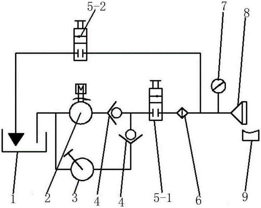
The invention discloses a lubricating oil pressure oiling hydraulic test stand and belongs to the technical field of structural design of airplane ground oiling equipment. The lubricating oil pressure oiling hydraulic test stand is used for performance testing of connectors of the airplane ground oiling equipment, lubricating oil in an oil tank is conveyed to a holding valve through one-way valves by a mechanical pump or a hand pump to control connection or disconnection, then the oil is communicated with an oil filter to achieve filtering of the lubricating oil and is divided into two oil paths at the position, one oil path forms an oil returning path through a holding valve, the other oil path is connected with a test connector through a pressure gage, and the leakage amount in the test is measured through a container. The lubricating oil pressure oiling hydraulic test stand is simple in structure, convenient to manufacture, high in stability, safe, reliable and capable of carrying out leakage test under the normal temperature, leakage test under the extreme environment condition, leakage test after loads are applied, intensity leakage test and circulating leakage test on the connectors of the airplane ground oiling equipment, thereby finishing comprehensive technical evaluation of a ground connection mouth and the connector on an airplane.

Description

technical field [0001] The invention relates to the technical field of structural design of aircraft ground refueling equipment, in particular to a lubricating oil pressure refueling hydraulic test bench, which is used for performance testing of joints of aircraft ground refueling equipment. Background technique [0002] Aircraft refueling methods are divided into two types: gravity refueling and pressure refueling. Gravity refueling is to use the oil's own gravity to refuel. The refueling cap is generally opened on the fuselage. When refueling, the cap needs to be opened. The refueling equipment is simple, but there are the following deficiencies : [0003] (1) Long refueling time, low efficiency, and high labor intensity for maintenance personnel; [0004] (2) The mouth cover is opened on the upper part of the aircraft. When refueling, a ladder is required to climb up the aircraft to refuel. The maneuverability is poor, and it is easy to cause unsafe factors and other def...

Claims


Application Information

Patent Timeline
IPC IPC(8): F15B19/00
Inventor 窦志伟
Owner SHENYANG AIRCRAFT DESIGN INST AVIATION IND CORP OF CHINA
Learn More