
Hotel washhouse ice source heat pump energy-saving drying system

A technology for drying systems and laundry rooms, applied in heat recovery systems, energy-saving heating/cooling, washing devices, etc., can solve problems such as destroying the drying environment, energy consumption, and cold air backflow, and achieve cost reduction, compact structure, and energy consumption. low effect

Inactive Publication Date: 2016-02-17
CHONGQING BINGYUANHONG ENERGY SAVING TECH DEV CO LTD
View PDF0 Cites 0 Cited by
  • Summary
  • Abstract
  • Description
  • Claims
  • Application Information

AI Technical Summary

Problems solved by technology

Especially in winter, or in a colder environment in the north, if the outside temperature is lower than 5°C and the surface temperature of the heat transfer tube is lower than 0°C, the moisture in the air will condense into frost on the surface of the heat transfer tube. Thick, it will block the air flow channel, significantly reduce the heat pump heat absorption from the air through the evaporator, resulting in the reduction of the heating coefficient and operation reliability of the air source heat pump, therefore, the existing drying system needs to be decomposed Frost operation, that is, the high-temperature and high-pressure refrigerant flows into the evaporator to achieve the defrosting effect, but due to the conversion of the heat exchange effect between the condenser and the evaporator, the dry hot air originally supplied becomes cold air, and this process will make the cold air Inverting, destroying the original dry environment, also consumes a lot of energy

Method used


Image

  • Hotel washhouse ice source heat pump energy-saving drying system

Examples


Embodiment Construction

[0009] In order to make the technical means, creative features, goals and functions achieved by the present invention clearer and easier to understand, the present invention will be further elaborated below in conjunction with the accompanying drawings and specific embodiments:

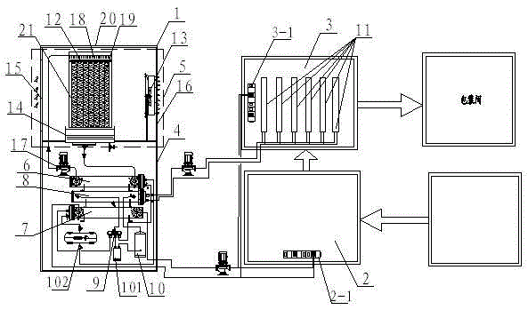
[0010] As shown in Figure 1, the present invention includes a refrigerant agent external machine 1, an ice source drying chamber 2 and an ice source ironing chamber 3, and the refrigerant agent external machine 1 includes an external machine shell 4, an air exchanger 5, and a primary exchanger 6. The secondary exchanger 7 and the heat recovery exchanger 8, the air exchanger 5, the primary exchanger 6, the secondary exchanger 7 and the heat recovery exchanger 8 are installed in the outer casing 4, and the air exchanger 5 The ice source solution circulates in the primary exchanger 6 to exchange heat with the refrigerant in the primary exchanger 6, and the refrigerant outlet of the primary exchanger 6 is ...


PUM


Abstract

The invention discloses a hotel washhouse ice source heat pump energy-saving drying system which comprises a refrigerant outer machine, an ice source drying room and an ice source ironing room. The refrigerant outer machine comprises an outer machine shell, and an air exchanger, a primary exchanger, a secondary exchanger and a heat recovery exchanger which are installed in the outer machine shell. A water inlet and a water outlet of the secondary exchanger are communicated with a refrigerant pipe of a combined air conditioner in the ice source drying room and a refrigerant pipe of a combined air conditioner in the ice source ironing room respectively. A water inlet and a water outlet of the heat recovery exchanger are communicated with refrigerant pipes of multiple sets of ironing devices in the ice source ironing room respectively. A refrigerant medium which will not be frozen at -30 DEG C exchanges heat with air and then is used as a heat exchange medium, so that a heat exchange source is provided for follow-up equipment, energy consumption is low, and the cost is reduced; the residual heat can be returned to water to be used as a secondary heat exchange source, the refrigerating and heating function can be provided for the indoor part, and the system is suitable for various regions.

Description

technical field [0001] The present invention belongs to the field of ice source technology, specifically an ice source heat pump energy-saving drying system. Background technique [0002] The existing hotel laundry room drying system mainly compresses the gaseous refrigerant into a high-temperature and high-pressure gaseous refrigerant through a compressor, and then sends it to the condenser to dissipate heat to become a normal-temperature and high-pressure liquid refrigerant. During this process, the condenser emits The heat is transported to the drying chamber through the fan, and then the liquid refrigerant enters the evaporator through the capillary tube. After the refrigerant reaches the evaporator from the capillary tube, the space suddenly increases and the pressure decreases, and the liquid refrigerant will vaporize and become a gaseous state. The low-temperature refrigerant absorbs a large amount of heat, and the evaporator becomes cold, and the water vapor in the a...

Claims


Application Information

Patent Timeline
IPC IPC(8): D06F58/10D06F58/20
CPCY02B30/52D06F58/10D06F58/20
Inventor 李开年曾斌
Owner CHONGQING BINGYUANHONG ENERGY SAVING TECH DEV CO LTD
Learn More