Eureka AIR delivers breakthrough ideas for toughest innovation challenges, trusted by R&D personnel around the world.

Spiral scraper structure

A spiral scraper technology, applied in the field of spiral scraper structure, can solve problems such as waste, poor quality of paint production, time-consuming and labor-intensive problems, and achieve the effect of avoiding waste

Active Publication Date: 2016-02-17
徐州天骋智能科技有限公司
View PDF8 Cites 8 Cited by
  • Summary
  • Abstract
  • Description
  • Claims
  • Application Information

AI Technical Summary

Problems solved by technology

After the colloidal dispersion enters the equipment, it sticks to the cylinder wall or tube wall of the equipment. After the production process is completed, there will always be a part of the dispersion sticking to the equipment. If this part of the dispersion cylinder sticking in the equipment is not cleaned If it is removed, the dispersion will form agglomerates in the equipment, which will affect the production of coatings and be detrimental to the quality of coating production
[0003] Since the barrels of these devices are mostly cylindrical or circular tube-shaped, the prior art mostly uses a linear scraper to make the scraper touch the inner wall of the circular cavity of the equipment, and constantly rotate the scraper to scrape off the viscous dispersion tube. If the scraper has slight defects such as deformation or gaps, the sticky dispersion at the defect will not be able to be scraped off; at the same time, after the scraper scrapes off the dispersion, a part of the dispersion will stick to the scraper, and the dispersion on the scraper needs to be cleaned. , it will be time-consuming and labor-intensive if you use manual removal, and it will cause waste if you rinse it off directly

Method used


Image

  • Spiral scraper structure

Examples


Embodiment Construction

[0012] The present invention will be described in further detail below by means of specific embodiments:

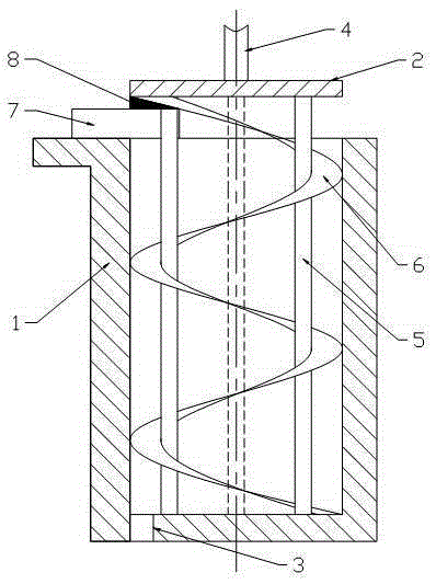
[0013] The reference signs in the accompanying drawings of the description include: barrel 1 , knife seat 2 , discharge port 3 , rotating shaft 4 , support rod 5 , scraper 6 , collecting box 7 , and scraper 8 .

[0014] Embodiment The structure of the spiral scraper is basically as attached figure 1 Shown: including barrel 1 and knife seat 2, the bottom of barrel 1 is provided with discharge port 3, knife seat 2 is disc-shaped, rotating shaft 4 is fixed at the center of the upper end surface of knife seat 2, and the bottom surface of knife seat 2 is along the There are 4 supporting rods 5 parallel to the axis of the barrel 1 evenly distributed in the circumferential direction of the end face. The fixed ends of the supporting rods 5 are fixed on the lower end surface of the knife holder. The length is equal to the length of the support rod 5, the upper end of the scraper ...


PUM

PropertyMeasurementUnit
Widthaaaaaaaaaa

Abstract

The invention discloses a spiral scraper structure. The spiral scraper structure comprises a cutter holder, wherein a rotation shaft is fixed to the circle center of the upper end surface of the cutter holder; a plurality of support rods parallel to an axis of a feed cylinder are uniformly distributed at the periphery of the circle center of the end surface on the lower end surface of the cutter holder; a support rod fixing end is fixed on the lower end surface of the cutter holder; a scraper is fixed to all the support rods; the scraper is spiral; the axial length of the scraper is equal to the length of the support rod; the upper end of the scraper is fixed to the lower end surface of the cutter holder; the outer edge of the scraper presses against the inner wall of the feed cylinder; the top of the feed cylinder is connected with a material collection box in a sliding manner in a direction vertical to the axis; the material collection box is detachably matched with the feed cylinder; a scraping plate is mounted on the material collection box and presses against the scraper. The invention aims to provide a spiral type scraper structure; linear scrapers are changed into spiral scrapers; the material collection box is additionally mounted on the scraper, so that the material can be scraped thoroughly even the scraper has defects; meanwhile, the dispersoid adhered to the scraper can be effectively collected; the waste is avoided.

Description

technical field [0001] The invention relates to the field of scrapers, in particular to a spiral scraper structure. Background technique [0002] During the production process of the paint, the pigment solid particles need to be crushed by external force and dispersed in the resin solution or emulsion to form a uniform and fine suspended colloidal dispersion. The production of coatings mainly uses dispersion equipment, grinding equipment, paint mixing equipment, filtration equipment, etc. After the colloidal dispersion enters the equipment, it sticks to the cylinder wall or tube wall of the equipment. After the production process is completed, there will always be a part of the dispersion sticking to the equipment. If this part of the dispersion cylinder sticking in the equipment is not cleaned If it is removed, the dispersion will form agglomerates in the equipment, which will affect the production of coatings and be detrimental to the quality of coating production. [00...

Claims


Application Information

Patent Timeline
IPC IPC(8): B08B9/087
CPCB08B9/0808
Inventor 吴全孙
Owner 徐州天骋智能科技有限公司
Why Eureka
Eureka Blog
Learn More