Microfluidic flow device

A shunt device and microfluidic technology, applied in the direction of fluid controllers, laboratory appliances, laboratory containers, etc., can solve the problems of experimental design that affect the effect of micro-liquid delivery, and the difficulty of uniform spreading and dispersion of water flow, etc., to achieve a solution The problem of micro liquid shunting, easy to realize, and the effect of simple principle

Active Publication Date: 2017-05-03
TECHNICAL INST OF PHYSICS & CHEMISTRY - CHINESE ACAD OF SCI
View PDF6 Cites 0 Cited by
  • Summary
  • Abstract
  • Description
  • Claims
  • Application Information

AI Technical Summary

Problems solved by technology

However, when the size of the microcavity is less than 0.50mm, due to the effect of water cohesion and adhesion, it is difficult for the water flow to spread evenly and disperse, and it only flows down along the central part and along the tooth-shaped groove.
This can seriously affect the delivery of microfluidics and the intended experimental design

Method used


Image

  • Microfluidic flow device
  • Microfluidic flow device
  • Microfluidic flow device

Examples


Embodiment Construction

[0014] In order to illustrate the present invention more clearly, the present invention will be further described below in conjunction with preferred embodiments and accompanying drawings. Similar parts in the figures are denoted by the same reference numerals. Those skilled in the art should understand that the content specifically described below is illustrative rather than restrictive, and should not limit the protection scope of the present invention.

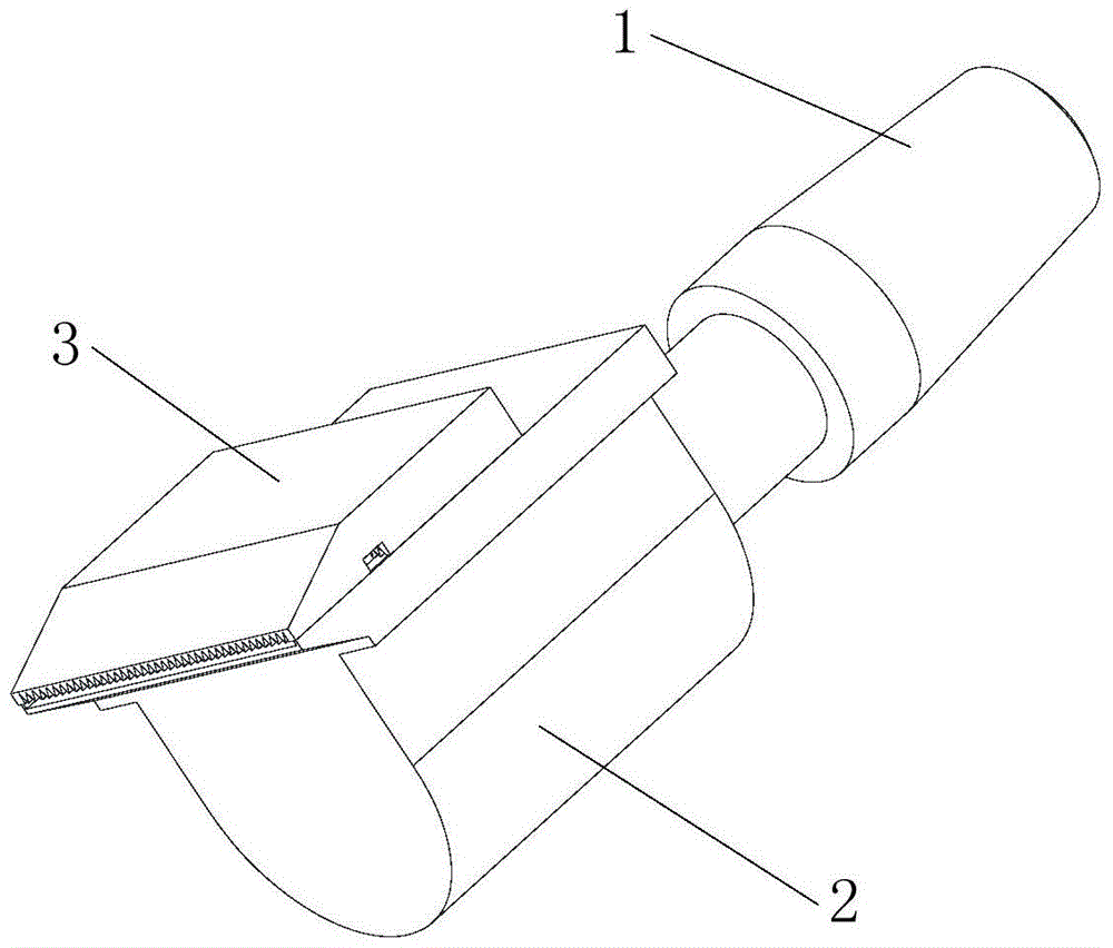
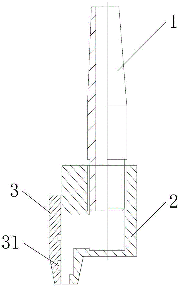
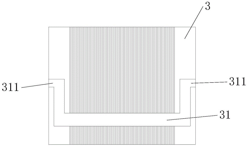
[0015] Such as figure 1 As shown, a microfluidic shunting device includes: a micro output liquid bile duct 1 providing a small amount of liquid, a micro flow liquid supply seat 2 and a micro flow guide template 3; the micro flow liquid supply seat 2 communicates with the micro output liquid bile duct 1, The micro-flow guide template 3 is arranged on the micro-flow liquid supply seat 2 for leading out liquid; near the lower port of the micro-flow guide template 2, a U-shaped groove 31 is horizontally opened, and the depth o...


PUM


Abstract

The invention discloses a microfluidic flow distributor, comprising a micro liquid outlet duct for providing micro liquid, a micro fluid supply base communicated with the micro liquid outlet duct, and a micro liquid guide template arranged on the micro fluid supply base for guiding liquid out. A U-shaped groove is transversely arranged close to the lower port of the micro guide template and openings are formed in two ends of the U-shaped groove. By adopting the structure, the U-shaped groove can act as a transverse capillary, thus micro fluid can transversely diffuse toward two ends of the U-shaped groove, and flow outwards along the gap in each lower tooth when the U-shaped groove is fully filled. Openings in two ends of the U-shaped groove are far less than the lower outlet in area and are higher in position, thus no water overflows from the upper part.

Description

technical field [0001] The invention relates to a distribution device for trace liquid in a trace control system. Background technique [0002] The micro-quantity control system can realize the transportation, separation and reaction of micro-volume liquid, which is of great significance for the design and realization of some precise experiments. However, when the size of the microcavity is less than 0.50 mm, due to the effect of water cohesion and adhesion, it is difficult for the water flow to spread evenly and disperse, and it only flows down along the central part and along the tooth-shaped groove. This will seriously affect the delivery effect of micro-fluids and the intended experimental design. Contents of the invention [0003] The technical problem to be solved by the present invention is to provide a microfluidic flow distribution device for uniform flow distribution of trace liquids. [0004] In order to solve the problems of the technologies described above, ...

Claims


Application Information

Patent Timeline
Patent Type & Authority Patents(China)
IPC IPC(8): B01L3/00
CPCB01L3/50273B01L3/561B01L2300/0861B01L2400/0406
Inventor 江雷徐国栋王京霞
Owner TECHNICAL INST OF PHYSICS & CHEMISTRY - CHINESE ACAD OF SCI
Why Eureka
Try Eureka