
Camera apparatus pointing direction control device

A technology for camera equipment and orientation control, which is applied in the field of communications and can solve the problem of inability to adjust the shooting angle of camera equipment in real time.

Inactive Publication Date: 2016-02-10
GUANGZHOU EHANG INTELLIGENT TECH
View PDF0 Cites 6 Cited by
  • Summary
  • Abstract
  • Description
  • Claims
  • Application Information

AI Technical Summary

Problems solved by technology

[0005] Based on this, it is necessary to provide a camera device pointing and azimuth control device for the technical problem that the existing control device cannot adjust the shooting angle of the camera device in real time

Method used


Image

  • Camera apparatus pointing direction control device
  • Camera apparatus pointing direction control device
  • Camera apparatus pointing direction control device

Examples


Embodiment Construction

[0016] In order to further illustrate the technical means adopted by the present invention and the achieved effects, the technical solutions of the present invention will be clearly and completely described below in conjunction with the accompanying drawings and preferred embodiments.

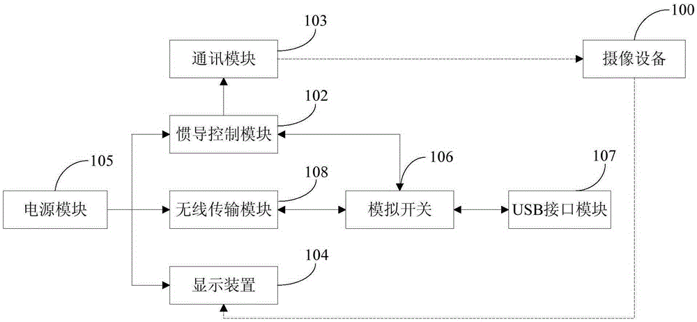
[0017] Such as figure 1 as shown, figure 1 It is a structural schematic diagram of an imaging equipment pointing and azimuth control device according to an embodiment of the present invention.

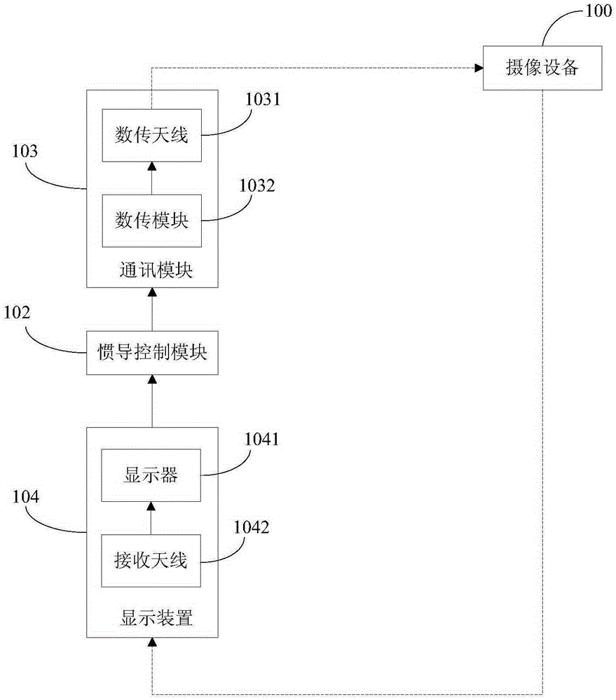
[0018] A camera device pointing and azimuth control device, comprising: a wearable device 101, an inertial navigation control circuit 102, a communication module 103 and a display device 104;

[0019] The inertial navigation control circuit 102 is connected to the communication module 103, the wearable device 101 is worn at the user's eye position, and the communication module 103 and the display device respectively communicate with the imaging device through wireless means;

[0020] The inertial navi...


PUM


Abstract

The invention relates to a camera apparatus pointing direction control device comprising a wearing apparatus, an inertial navigation control circuit, a communication module and a display device. The inertial navigation control circuit is connected with the communication module. The wearing apparatus is worn at the position of the eyes of a user. The communication module and the display device communicate with a camera apparatus wirelessly. The inertial navigation control module arranged on the wearing apparatus acquires the posture change information of the wearing apparatus, generates a direction control command according to the posture change information and transmits the direction control command to the camera apparatus through the communication module. The camera apparatus performs shooting angle adjustment according to the direction control command. The display device displays an obtained image captured by the camera apparatus for the user, thus providing reference for wearing apparatus posture adjustment for the user. With the technical solution, the camera apparatus pointing direction control device enables the shooting angle of the camera apparatus to be adjusted timely according to the posture change information of the wearing apparatus.

Description

technical field [0001] The invention relates to the field of communication technology, in particular to a device for controlling the pointing direction of an imaging device. Background technique [0002] Aerial photography, also known as aerial photography or aerial photography, refers to taking pictures of the earth's landforms from the air to obtain a top view. This picture is an aerial photo. Aerial cameras can be controlled by the photographer, or they can be shot automatically or remotely. The platforms used for aerial photography include model aircraft, airplanes, helicopters, unmanned aerial vehicles, hot air balloons, small spaceships, rockets, kites, parachutes, etc. [0003] In the previous aerial photography work, the user can take images through the camera equipment installed on the aircraft, and wirelessly transmit the images captured by the camera equipment to the display device on the ground. Manipulate the controller on the aircraft to make it adjust the sh...

Claims


Application Information

Patent Timeline
IPC IPC(8): H04N5/232G05D1/00H04N7/18
CPCB64D47/08G05D1/08G05D1/10H04N7/18G05D1/0011H04N7/185H04N23/66H04N23/698G05D1/00G05D3/00
Inventor 胡华智朱剑锋
Owner GUANGZHOU EHANG INTELLIGENT TECH
Learn More