
Method for utilizing thin-layer interference amplitude recovery to identify oil and gas reservoir

An amplitude recovery, oil and gas reservoir technology, applied in seismology for well logging, earthwork drilling, wellbore/well components, etc., can solve the influence of thickness reduction factor, without considering reservoir thickness, oil and gas reservoir effectiveness Limits and other issues, to achieve the effect of easy operation, strong guidance, and good fit

Active Publication Date: 2016-02-10
CHINA PETROLEUM & CHEM CORP +1
View PDF7 Cites 13 Cited by
  • Summary
  • Abstract
  • Description
  • Claims
  • Application Information

AI Technical Summary

Problems solved by technology

[0008] However, in specific oil and gas exploration work, the use of amplitude seismic attributes to identify oil and gas reservoirs is generally limited to the extraction of amplitude seismic attributes along the layer, because the amplitude attribute is a combination of reservoir oil and gas properties, reservoir thickness, reservoir physical properties, etc. It reflects that when the thickness of the reservoir changes greatly and the reservoir is thin, due to the complex interference effect of the reflection wave of the thin reservoir, the amplitude of the seismic response of the reservoir with different thickness will change by complex changes
Because the influence of reservoir thickness on the amplitude value is not considered, the effectiveness of identifying oil and gas reservoirs using previous methods is very limited
For the identification of oil and gas reservoirs under the condition of changing reservoir thickness, there is currently no effective method to reduce the influence of thickness factors on amplitude values.

Method used


Image

  • Method for utilizing thin-layer interference amplitude recovery to identify oil and gas reservoir
  • Method for utilizing thin-layer interference amplitude recovery to identify oil and gas reservoir
  • Method for utilizing thin-layer interference amplitude recovery to identify oil and gas reservoir

Examples


Embodiment 1

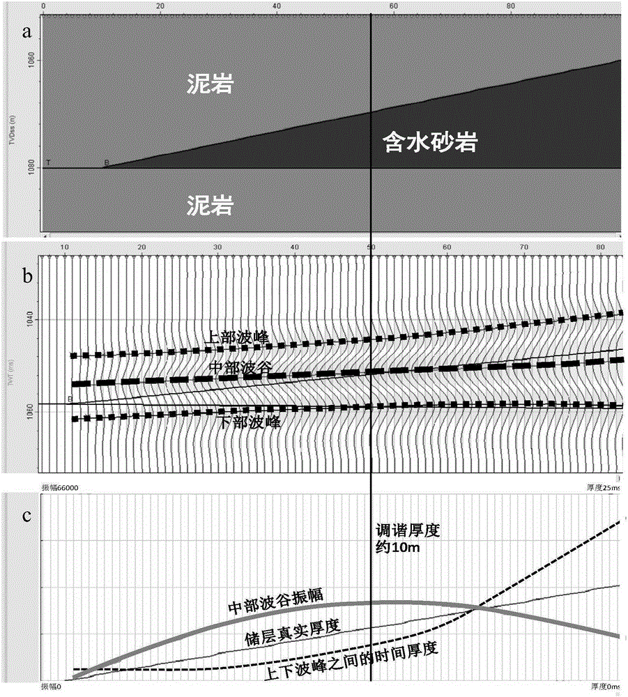
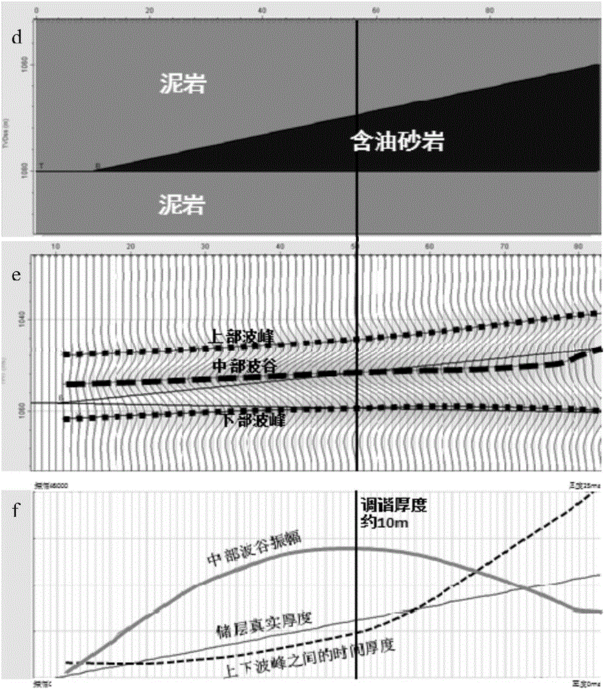
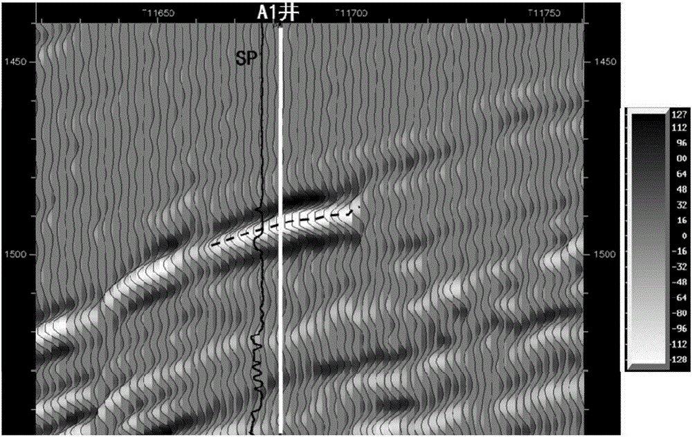
[0039] The area of ​​the 3D seismic data in the work area is 56km 2 , two exploratory wells, A1 and A2, have been drilled. The target layer of Well A1 is a lithologic oil reservoir, and Well A2 has not encountered any oil reservoir, and there is no reservoir on the target layer; The thickness varies greatly (thickness ranges from 1 to 9m). In exploration practice, it is found that the reservoir thickness has a significant impact on the amplitude, and the use of amplitude attributes to identify reservoirs has a certain degree of ambiguity.

[0040] The method for identifying oil and gas reservoirs using thin layer interference amplitude restoration in this embodiment is to identify oil and gas reservoirs in the above work area, including the following steps:

[0041] 1) According to the drilling data of the work area and adjacent area, the velocity of the mudstone is 2747m / s and the density is 2.29g / cm 3 , the velocity of the water layer is 2554m / s, and the density is 2.11g / cm...


PUM


Abstract

The invention discloses a method for utilizing thin-layer interference amplitude recovery to identify an oil and gas reservoir. The method comprises a step of: 1) establishing wave impedance models of a reservoir under different conditions, carrying out forward modeling, and finding out the relation between an event time thickness and an amplitude value; 2) tracking a seismic reflection event which can best reflect the target reservoir, and extracting a horizon amplitude plane graph, superposing the horizon amplitude plane graph with a construction drawing, and identifying a target trap; 3) tracking two up-down adjacent seismic reflection events in the target trap; 4) according to three obtained seismic interpretation horizons, calculating the event time thickness; 5) according to the relation between the event time thickness and the amplitude value, obtaining a seismic amplitude plane graph; and 6) subtracting the seismic amplitude plane graph obtained in the step 5) from the seismic amplitude plane graph obtained in the step 2), obtaining an amplitude attribute map after amplitude recovery, and judging whether the target trap contains the oil and gas reservoir on the map. By adopting the method, the interference of the reservoir thickness to the oil and gas reservoir identification is effectively reduced, and the oil and gas reservoir can be identified more effectively.

Description

technical field [0001] The invention belongs to the technical field of oil and gas exploration and development, and in particular relates to a method for identifying oil and gas reservoirs by using thin-layer interference amplitude restoration. Background technique [0002] In oil and gas exploration and development, a thin layer refers to a formation whose top and bottom reflected waves cannot be distinguished clearly, and the interference effect of a thin layer refers to the mutual interference and superposition of the primary reflection wave at the top of the thin layer and the multiple waves of all levels in the thin layer the resulting effect. When the underground reservoir is thin, the seismic reflection waves at the top and bottom interfaces of the reservoir will interfere with each other and superimpose. When the thickness of the thin layer changes continuously in the lateral direction, the interference effect of the reflection waves will show complex changes. Due t...

Claims


Application Information

Patent Timeline
IPC IPC(8): G01V1/28E21B49/00G01V1/40
Inventor 王鹏飞杨春峰肖学胡宇
Owner CHINA PETROLEUM & CHEM CORP
Learn More