
MEMS-based conformal air speed sensor

A sensor and pressure sensor technology, applied in the field of sensors, can solve problems such as blockage and pitot tube icing, and achieve the effect of preventing icing, reducing the possibility of icing, and reducing the possibility of blockage

Active Publication Date: 2016-02-10
THE BOEING CO
View PDF5 Cites 11 Cited by
  • Summary
  • Abstract
  • Description
  • Claims
  • Application Information

AI Technical Summary

Problems solved by technology

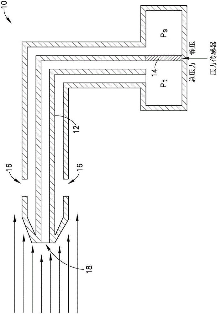
The system disclosed in detail below solves the problem of icing or clogging of pitot tubes by creating an outer surface on the aircraft that carries the air and measures the pressure differential between the pressure of the airflow and the static pressure

Method used


Image

  • MEMS-based conformal air speed sensor
  • MEMS-based conformal air speed sensor
  • MEMS-based conformal air speed sensor

Examples


Embodiment Construction

[0031] For purposes of illustration, embodiments of systems and methods for measuring space velocity using MEMS-based pressure sensors will now be disclosed in detail. However, alternative pressure sensors of suitable size and sensitivity, which are not fabricated using improved semiconductor device fabrication techniques, may be utilized.

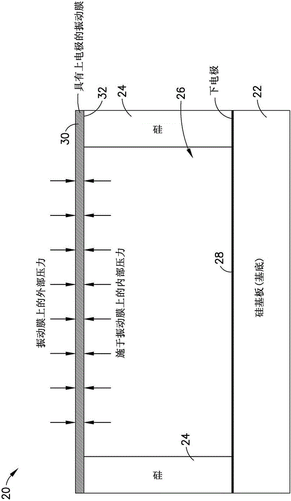
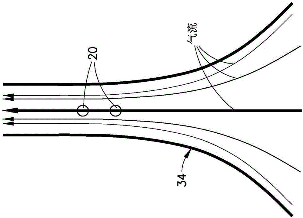
[0032]According to embodiments disclosed herein, the system includes an array of MEMS capacitive differential pressure sensors with their associated signal conditioning, and a locally flexible conformal surface structure with input for the MEMS capacitive differential pressure sensors and still air Airways and holes for inhalation. The system further includes a processor that calculates a final airspeed estimate. Preferably, means for heating the conformal surface (to prevent airway icing) are provided. If the conformal surface is made of metal or other thermally conductive material, the heating method may include attaching a resistive h...


PUM


Abstract

The invention discloses an MEMS-based conformal air speed sensor. Systems and methods for measuring air speed which solve the problem of icing or blockage by creating an exterior surface on an aircraft that channels air and measures the pressure difference of the pressure through the airflow and the static pressure. This exterior surface cannot be blocked easily because air is always flowing when the aircraft is in motion, any external matter that could be on the exterior surface is readily visible, and the exterior surface can be heated to prevent icing. In addition, the exterior surface is made of a flexible material that is able to conform closely to the exterior shape of the aircraft. The preferred embodiments comprise microelectromechanical system pressure sensors placed under the air channels for measuring the pressure difference in each channel and an air speed processor for transforming the pressure differences into an air speed estimate.

Description

technical field [0001] The present disclosure generally relates to sensors for measuring the velocity of an aircraft relative to its surrounding air mass (hereinafter "airspeed"). Background technique [0002] Aircraft require in-flight self-airspeed measurements for aircraft maneuvering, aerodynamic calculations, and possible stalls. This is usually done using a pitot tube, which consists of a tube that points directly into the airflow. Using the internal fluid compressed under air pressure, the fluid pressure can be measured and used to calculate the stagnation pressure of the air. To calculate the airflow velocity, compare to the static pressure measured from the static port of the feed barometer. Then using Bernoulli's equation, the dynamic pressure (and therefore, the space velocity) can be calculated. [0003] Modern pitot tubes are heated but still have problems with freezing and clogging which make their use problematic under certain conditions. More specifically...

Claims


Application Information

Patent Timeline
Patent Type & Authority Applications(China)
IPC IPC(8): G01P5/14
CPCG01P5/14G01F1/46G01P5/00G01F1/383
Inventor 加里·A·雷
Owner THE BOEING CO
Learn More