
A new type of temperature sensor

A temperature sensor, a new type of technology, applied in thermometers, thermometer parts, instruments, etc., can solve problems such as the lack of real reflection of the temperature of the cooker, the influence of the use of the cooker, and the drift of the temperature curve, so as to reduce unfavorable factors and facilitate The effect of high precision in assembly and testing

Active Publication Date: 2018-03-30
VATTI CORP LTD
View PDF8 Cites 0 Cited by
  • Summary
  • Abstract
  • Description
  • Claims
  • Application Information

AI Technical Summary

Problems solved by technology

[0002] The temperature sensors commonly used in civilian gas stoves, especially the temperature measurement devices for smart stoves that use automatic temperature measurement as the control signal source, most of them have low temperature measurement accuracy, especially in complex heating environments and long-term working conditions. The temperature curve is prone to "drift", and the temperature in the pot heated by the cooker cannot be truly reflected, so it can only be corrected in the relevant program of the controller, which will affect the use effect of the cooker

Method used


Image

  • A new type of temperature sensor
  • A new type of temperature sensor
  • A new type of temperature sensor

Examples


Embodiment 1

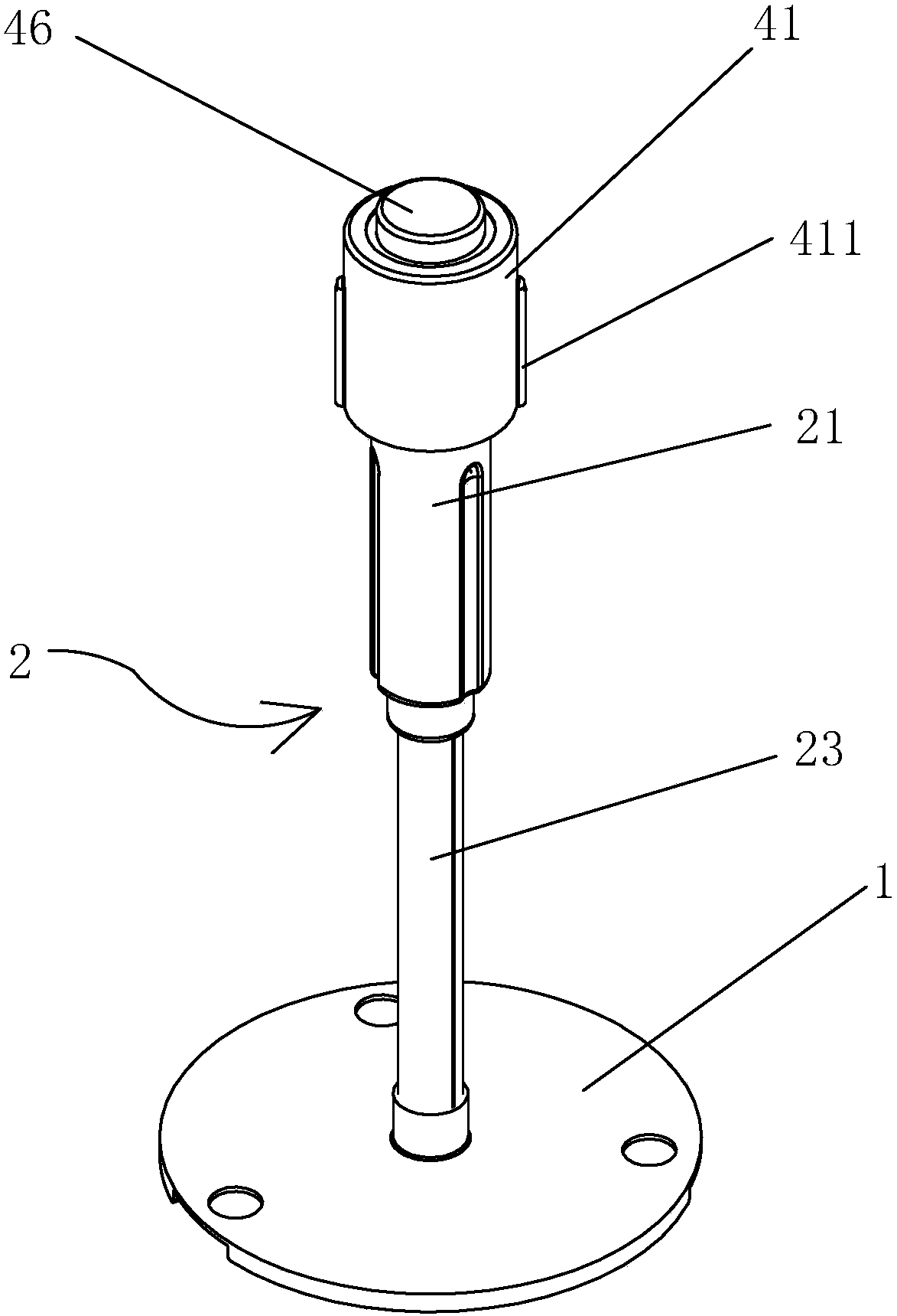
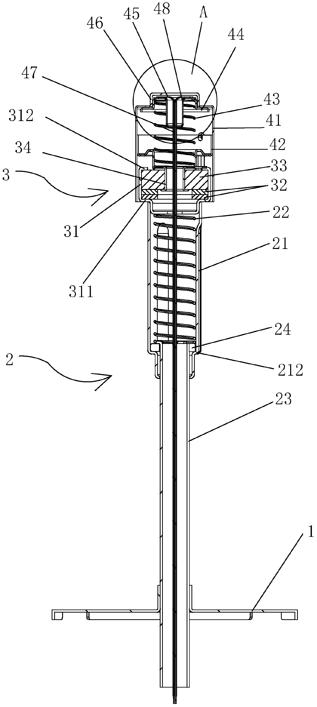
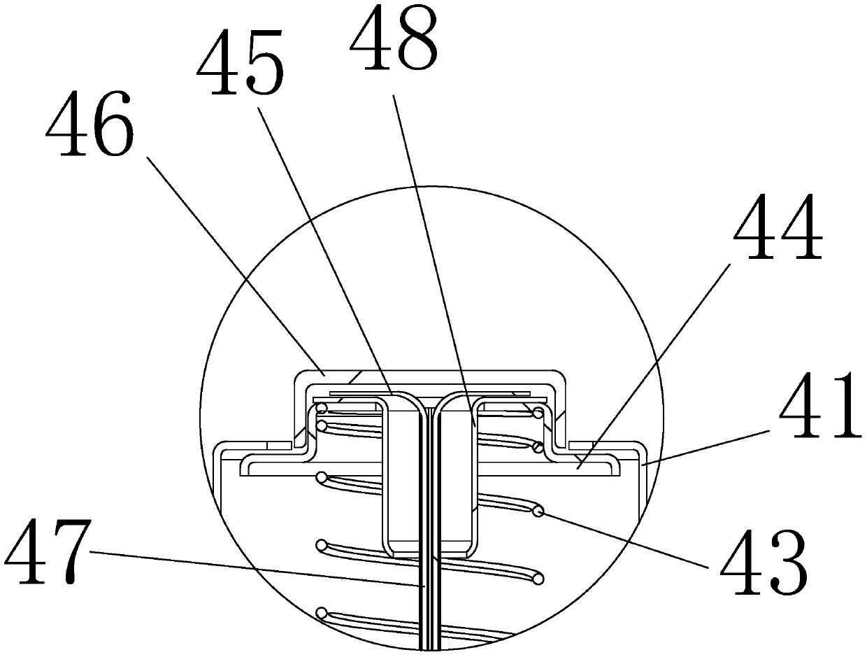
[0039] Such as Figure 4 As shown, the probe seat 44 is pressed inside the bushing 41, so that the spring seat 42, the probe seat 44, and the bushing 41 form a cavity structure. In the free state of the non-working state, the probe seat 44 in the cavity is closely attached to the upper end surface of the bushing 41 under the action of elastic force to prevent the intrusion of foreign oil, smoke and other sundries. In the working state, the high-temperature heating pot body, the bottom of the pot presses the probe 46, the probe base 46 is separated from the upper surface of the bushing 41, the probe 46 is flattened with the bottom of the pot so as to independently sense the temperature of the bottom of the pot, and the inner wall of the bushing 41 separates the probe 46 inside from the outside world , prevent external high temperature conduction in the transverse direction, and radiate to the probe seat 42, wire seat 48 and probe 46 in the cavity; the glass-ceramic 33 and the g...

Embodiment 2

[0041] Such as Figure 11 and Figure 12 As shown, the bushing 41 is provided with an outer cover.

[0042] Such as Figure 12As shown, the probe seat 44 is pressed in the bushing 41, so that the spring seat 42, the probe seat 44, the bushing 41 and the outer cover of the sliding sleeve form two cavity structures. The inner cavity and the outer cavity are free in the non-working state. Next, the probe seat 44 in the inner cavity and the upper end surface of the sliding sleeve cover are tightly fitted under the action of the spring force to prevent foreign oil, smoke and other sundries from invading. The bottom presses the probe 46, the probe base 44 is separated from the outer cover of the sliding sleeve, and the probe 46 is flattened with the bottom of the pot so as to sense the temperature of the bottom of the pot independently. Radiation to the inner cavity; glass ceramics 33 and glass fiber sheet 32 ​​prevent the conduction of temperature in the longitudinal direction; ...


PUM


Abstract

The invention discloses a novel temperature sensor, comprising a fixed plate, the top of the fixed plate is connected with a bushing with an opening on the top, a probe seat is arranged at the opening of the bushing, and the probe seat is connected with the probe seat inside the bushing. There is a one-way heat conduction assembly between the fixed plates, the top of the probe base is connected to the thermocouple and the probe in sequence from bottom to top, and the thermocouple is connected with the wire passing through the fixed plate, which is a kind of heating element that can be used in complex heating environments. And a temperature sensor that can truly sense the temperature inside the heated pot under long working conditions.

Description

[technical field] [0001] The invention relates to a novel temperature sensor. [Background technique] [0002] The temperature sensors commonly used in civilian gas stoves, especially the temperature measuring devices for intelligent stoves that use automatic temperature measurement as the control signal source, most of them have low temperature measurement accuracy, especially in complex heating environments and long-term working conditions. The temperature curve is prone to "drift", and the temperature in the pot heated by the cooker cannot be truly reflected. It can only be corrected in advance in the relevant programs of the controller, which will affect the use effect of the cooker. [Content of the invention] [0003] The invention overcomes the disadvantages of the above-mentioned technologies, and provides a temperature sensor capable of truly sensing the temperature inside the heated pot in a complex heating environment and in a long-time working state. [0004] To...

Claims


Application Information

Patent Timeline
Patent Type & Authority Patents(China)
IPC IPC(8): G01K1/14G01K1/18G01K7/02
Inventor 罗长兵程鸣潘叶江
Owner VATTI CORP LTD
Learn More