
Dynamic Calibration Method of Double-Star Sensor Carrier Mounting Matrix

A technology of double star sensor and installation matrix, applied in the field of astronomical navigation, can solve the problems of low and strict calibration accuracy, and achieve the effect of high calibration accuracy

Active Publication Date: 2018-03-30
UNIT 63680 OF PLA
View PDF5 Cites 0 Cited by
  • Summary
  • Abstract
  • Description
  • Claims
  • Application Information

AI Technical Summary

Problems solved by technology

There are two problems with this method: one is that the calibration accuracy of the rotation angle along the optical axis of the star sensor is relatively low; the other is that the calibration requires the carrier to be in a static condition and the conditions for obtaining the installation matrix are relatively strict

Method used


Image

  • Dynamic Calibration Method of Double-Star Sensor Carrier Mounting Matrix
  • Dynamic Calibration Method of Double-Star Sensor Carrier Mounting Matrix
  • Dynamic Calibration Method of Double-Star Sensor Carrier Mounting Matrix

Examples


Embodiment

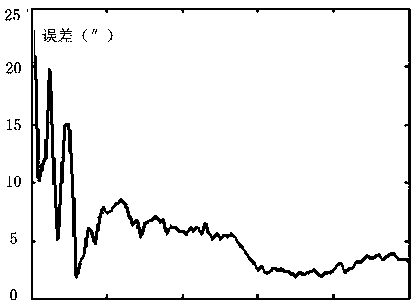
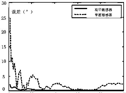
[0074] 1. Simulation test conditions and parameters

[0075] The star sensor parameters are shown in Table 1:

[0076] Table 1 Star sensor parameters

[0077]

[0078] The position and attitude information of the hull is shown in Table 2:

[0079] Table 2 Hull position and attitude information

[0080]

[0081] The stellar right ascension and declination information are shown in Table 3, in which stars 1-4 are in the field of view of star sensor A1, and stars 5-8 are in the field of view of star sensor A2.

[0082] Table 3 Stellar Positions

[0083]

[0084] Other parameters at the time of observation are shown in Table 4:

[0085] Table 4 Observation time related parameters

[0086]

[0087] The installation angle of the star sensor is shown in Table 5:

[0088] Table 5 Star sensor installation angle

[0089]

[0090] 2. Simulation test results and related data

[0091]

[0092]

[0093]

[0094]

[0095]

[0096]

[0097] 3. Simulatio...


PUM


Abstract

The invention relates to a method for dynamic calibration of a mounting matrix of two star sensors and carriers. The method comprises the following steps: I, calibrating a relative mounting matrix of the star sensors, and acquiring the relative position relationship between the star sensors; II, calibrating the mounting matrixes of the star sensors and the carriers, that is, carrying out united solution of the star sensors to acquire the position relationship between one star sensor and the corresponding carrier. The method can be used for solving the problem that the calibration precision of the rotation angles of the star sensors in optical axis directions is low when the two star sensors are used for calibrating the mounting matrixes separately; dynamic calibration can be realized under the condition that the carriers are in moving states. Therefore, the method is particularly suitable for dynamic calibration of shipborne star sensors.

Description

technical field [0001] The invention relates to a method for dynamic calibration of a double-star sensor installation matrix. It belongs to the field of celestial navigation. Background technique [0002] The star sensor takes the star as a reference object, and the detection unit captures the star map of the sky at a certain moment, and the data processing unit performs a series of processes such as star centroid extraction, star map recognition, star tracking, attitude calculation, etc., and finally It is a high-precision attitude measurement device to obtain high-precision attitude information of the star sensor relative to the inertial space. [0003] At present, star sensors are widely used in aerospace vehicle attitude measurement. With the maturity of high-precision and large-field star sensor technology, star sensors have been able to complete hull attitude measurement. [0004] Before the star sensor is used, the installation matrix between it and the carrier need...

Claims


Application Information

Patent Timeline
Patent Type & Authority Patents(China)
IPC IPC(8): G01C21/02G01C25/00
CPCG01C21/025G01C25/00
Inventor 焦宏伟张同双潘良周海渊赵李健刘新明王前学杜鹏桑海峰
Owner UNIT 63680 OF PLA
Learn More