
Improved solar receiver structure

A receiver, solar technology, applied in the field of improved panel and header arrangement, panel orientation, which can solve the problems of design increase, manufacturing constraints, receiver erection complexity, etc.

Inactive Publication Date: 2019-01-08
GENERAL ELECTRIC TECH GMBH
View PDF7 Cites 0 Cited by
  • Summary
  • Abstract
  • Description
  • Claims
  • Application Information

AI Technical Summary

Problems solved by technology

However, it will be apparent to those skilled in the art that in the process of creating such inboard header arrangements, other issues can be added to the design, such as manufacturing constraints, fluid drainage limitations, complexity of receiver erection, availability of receivers, etc. maintainability

Method used


Image

  • Improved solar receiver structure
  • Improved solar receiver structure
  • Improved solar receiver structure

Examples


Embodiment Construction

[0052]For a complete understanding of the present disclosure, reference should be made to the following detailed description, including the appended claims, taken in conjunction with the foregoing drawings. In the following detailed description, for purposes of explanation, numerous specific details are set forth in order to provide a thorough understanding of the present disclosure. However, it will be understood by those skilled in the art that the present disclosure may be practiced without limitation to these specific details. In other instances, structures and devices are shown in block diagram form only in order to avoid obscuring the disclosure. References to "one embodiment", "an embodiment" and "another embodiment" in this specification mean that the specific features, structures or characteristics described in conjunction with the embodiments are included in at least one embodiment of the present disclosure. The appearances of the phrase "in one embodiment" in vario...


PUM


Abstract

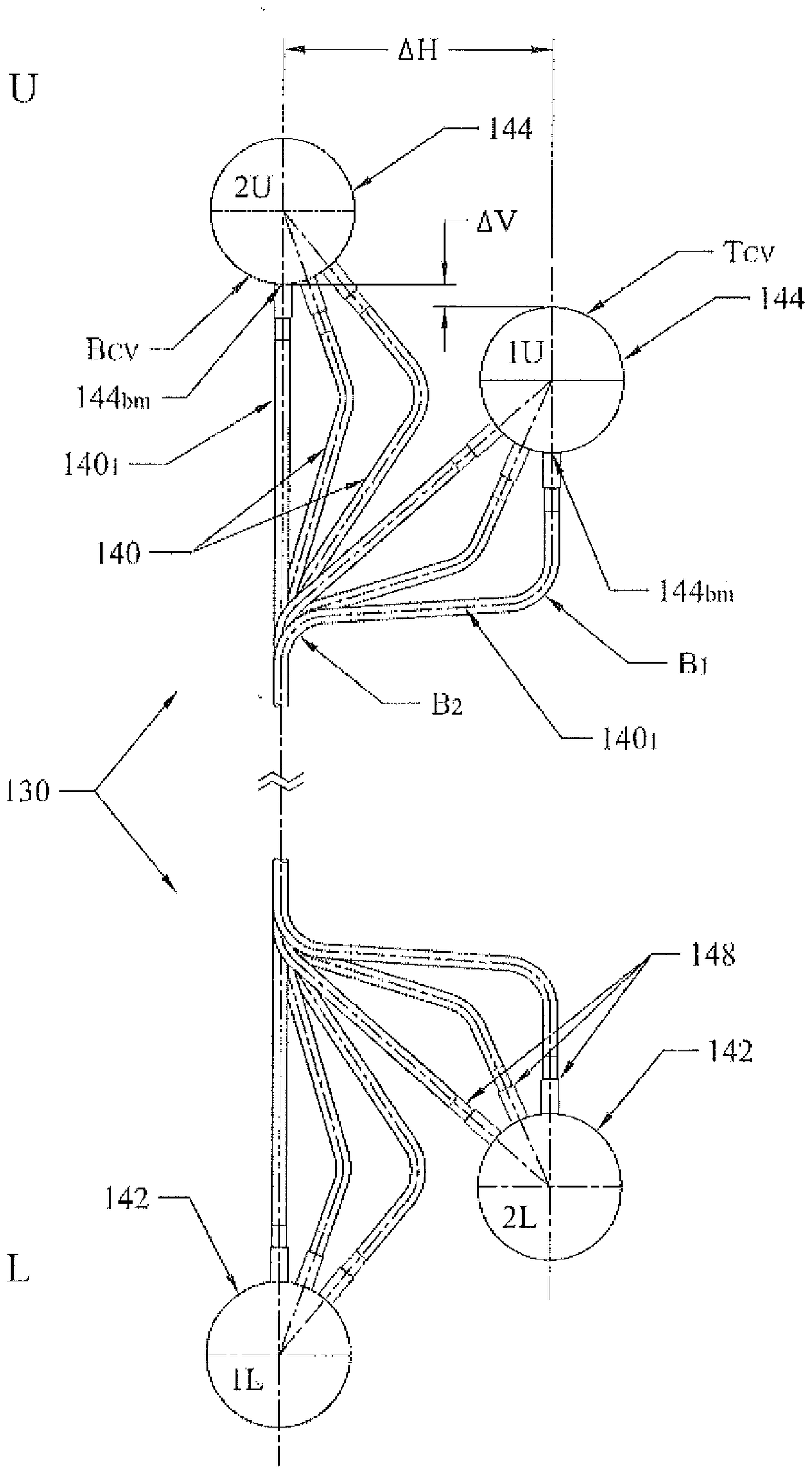
A solar receiver configuration (receiver) adapted to include a plurality of receiver heat transfer passes. Each pass includes a plurality of panels. Further, each panel includes a plurality of tubes, tangentially arranged, vertically extending between horizontally placed lower and upper headers. The headers, which are pipe assemblies with closed ends, of adjacent panels are horizontally and vertically offset one to another to form a substantially continuous tube surface. Such continuous tube surface enables solar heating of the fluid flow therefrom in at least a parallel flow arrangement and a serpentine flow arrangement.

Description

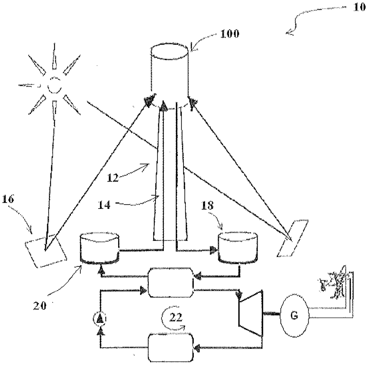
technical field [0001] The present invention relates to a solar central receiver for a centralized power tower plant, and more particularly to an improved panel and header arrangement and orientation of panels including heat transfer surfaces for a solar central receiver. Background technique [0002] In a typical arrangement of a concentrated solar power plant, a large field of heliostats is arranged around a solar central receiver (solar receiver) placed on a tower of considerable height, where the heliostats will Direct sunlight is focused onto a solar receiver, which provides heat to a heat transfer fluid, which is applied to generate steam to run a turbine and extract work to generate electricity. Solar receivers typically include various vertical panels, each having a fluid-carrying vertical conduit disposed between horizontally disposed headers for distributing the fluid into the conduits. The duct panel arrangement used to construct the solar receiver is very good f...

Claims


Application Information

Patent Timeline
Patent Type & Authority Patents(China)
IPC IPC(8): F24S10/70F24S80/30F24S20/20
CPCF24S10/74F24S10/742F24S20/20F24S80/30Y02E10/44F24S10/72Y02E10/40
Inventor C.J.勒奇R.G.帕内J.特维迪伊G.帕斯科A.达斯邓林D.麦格拉内P.伊尼戈R.J.特达卡
Owner GENERAL ELECTRIC TECH GMBH
Learn More