
Wing driving mechanism of a flapping wing aircraft

A driving mechanism and wing technology, applied in the field of flapping wing aircraft, can solve the problems such as the inability to flexibly change the angle of attack and the inability to achieve 8"-shaped flight, and achieve the effects of high wing driving efficiency, strong maneuverability and stable flight.

Active Publication Date: 2017-10-10
吴立群
View PDF6 Cites 0 Cited by
  • Summary
  • Abstract
  • Description
  • Claims
  • Application Information

AI Technical Summary

Problems solved by technology

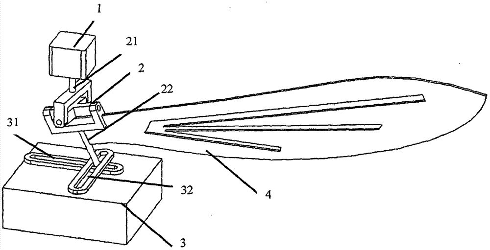
[0005] Based on the above-mentioned deficiencies in the prior art, the present invention proposes a wing drive mechanism of a flapping-wing aircraft to solve the problems that the original flapping-wing aircraft cannot achieve "8" flight and cannot flexibly change the angle of attack

Method used


Image

  • Wing driving mechanism of a flapping wing aircraft
  • Wing driving mechanism of a flapping wing aircraft
  • Wing driving mechanism of a flapping wing aircraft

Examples


Embodiment Construction

[0025] The following examples are only used to illustrate the technical solution of the present invention more clearly, but not to limit the protection scope of the present invention. Certain terms are used, for example, in the description and claims to refer to particular components. Those skilled in the art should understand that hardware manufacturers may use different terms to refer to the same component. The specification and claims do not use the difference in name as a way to distinguish components, but use the difference in function of components as a criterion for distinguishing. The subsequent description of the specification is a preferred implementation mode for implementing the present invention, but the description is for the purpose of illustrating the general principles of the present invention, and is not intended to limit the scope of the present invention. The scope of protection of the present invention should be defined by the appended claims.

[0026] T...


PUM


Abstract

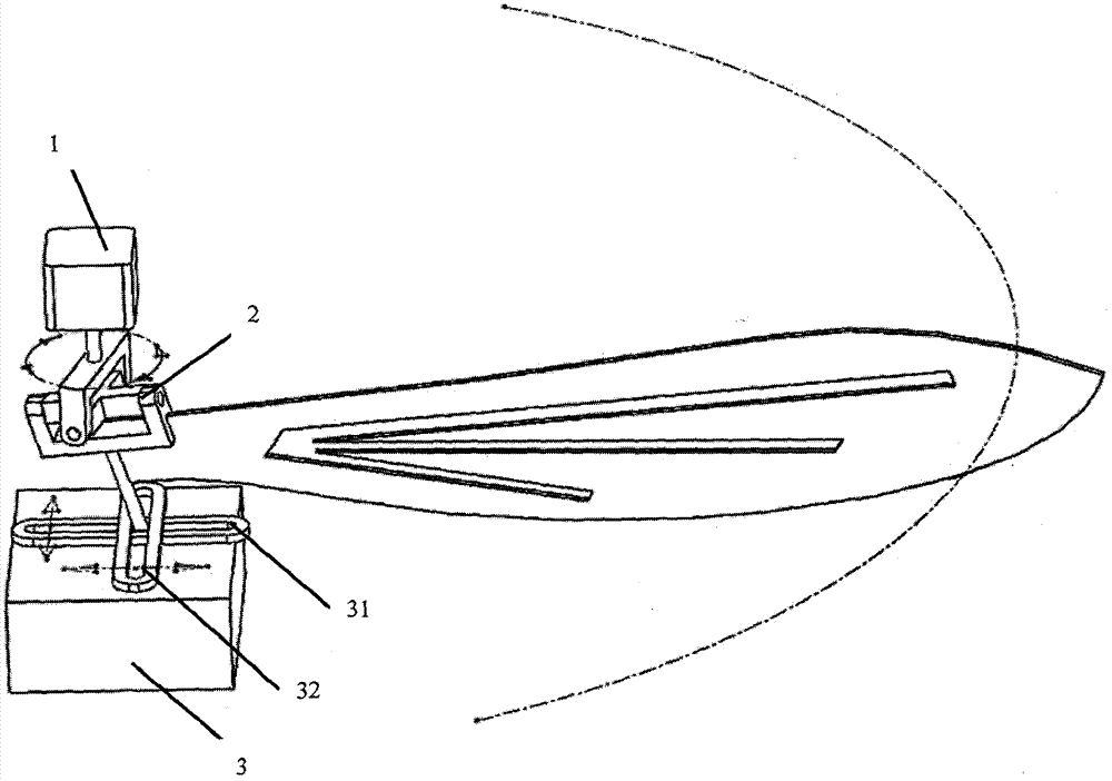
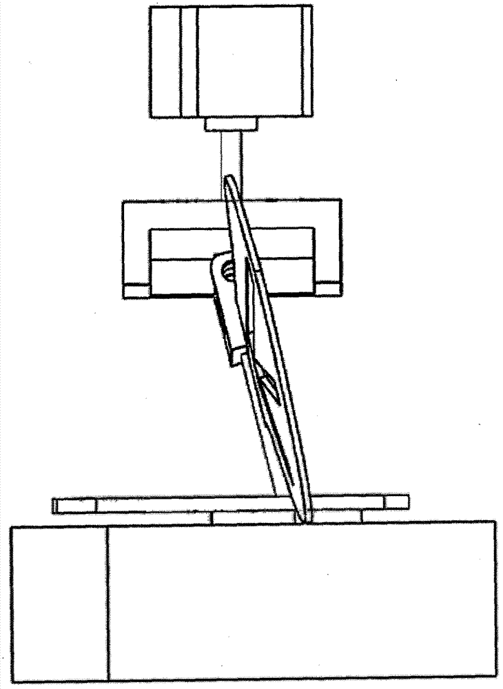
The invention discloses a wing drive mechanism of a flapping wing aircraft, which comprises: a drive device, a universal joint and a position control device connected in sequence, wherein the universal joint has a drive shaft and a driven shaft, and the slave Wings are connected to the driving shaft, one end of the driving shaft is connected to the driving device and rotates under the action of the driving device, one end of the driven shaft is connected to the position control device and is rotated under the action of the position control device movement, the driving device is equipped with a first position sensor for real-time perception of the movement position of the drive shaft, and the position control device is installed with a second position sensor for real-time perception of the movement position of the driven shaft. The movement position is also adjusted in real time according to the change of the movement position of the drive shaft. The invention solves the problems that the original flapping-wing aircraft cannot realize "8" flight and cannot flexibly change the angle of attack.

Description

technical field [0001] The invention relates to a flapping-wing aircraft, in particular to a wing driving mechanism of the flapping-wing aircraft. Background technique [0002] The flapping-wing aircraft refers to an aircraft that generates lift and forward force through the active movement of the wings like a bird. The flapping-wing aircraft flies by flapping its wings during flight. Compared with fixed-wing and rotary-wing flying, flapping-wing flight has the characteristics of taking off in situ or in a small field, good flight maneuverability and certain hovering performance in the air, and less energy consumption for long-distance flight. In the military, it can be used for enemy reconnaissance, target tracking, electronic interference, relay communication, active attack and defense, etc.; in civilian use, it can be used for environmental and disaster monitoring, traffic road monitoring, agricultural surveying, aerial photography, etc. [0003] The flapping wings in na...

Claims


Application Information

Patent Timeline
Patent Type & Authority Patents(China)
IPC IPC(8): B64C33/02
Inventor 吴立群
Owner 吴立群
Learn More