
Step height locking device and self-balancing handlebar rod with height step adjustment function

A locking device and high-level technology, which is applied to bicycle accessories, transportation and packaging, steering mechanisms, etc., can solve the problems of serious wear of the locking plate, excessive locking force, and displacement of the height of the bar, and reduce damage The degree, the locking effect is good, and the effect of reducing the weight of the device

Active Publication Date: 2016-02-10
NINGBO CHIKEWEI ELECTRONICS CO LTD
View PDF4 Cites 1 Cited by
  • Summary
  • Abstract
  • Description
  • Claims
  • Application Information

AI Technical Summary

Problems solved by technology

[0003] 1. The locking force is too large, the locking plate is severely worn, and the locking will fail after wearing
[0004] 2. The eccentricity of the locking needs to be adjusted accurately in order to adapt to the effective locking, and it may be improperly used by non-professionals
[0005] 3. Stepless locking, when the locking force is insufficient, the height of the lever may be displaced during use, causing risks

Method used


Image

  • Step height locking device and self-balancing handlebar rod with height step adjustment function
  • Step height locking device and self-balancing handlebar rod with height step adjustment function
  • Step height locking device and self-balancing handlebar rod with height step adjustment function

Examples


Embodiment 1

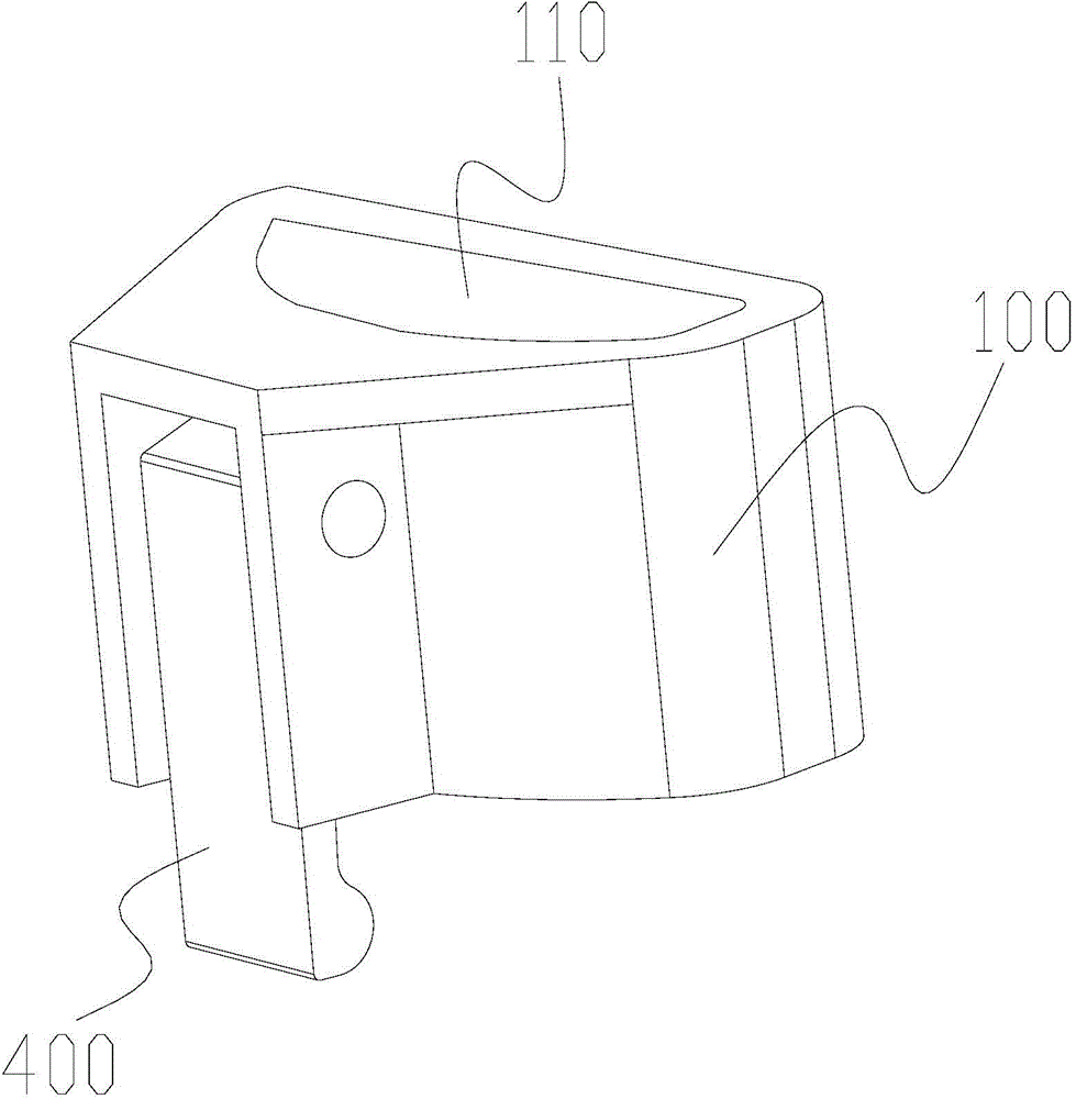
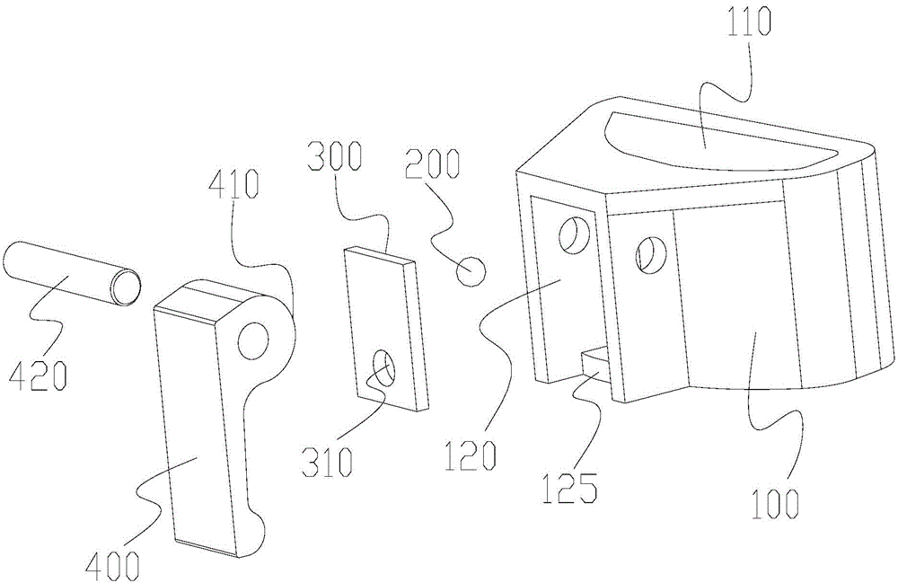
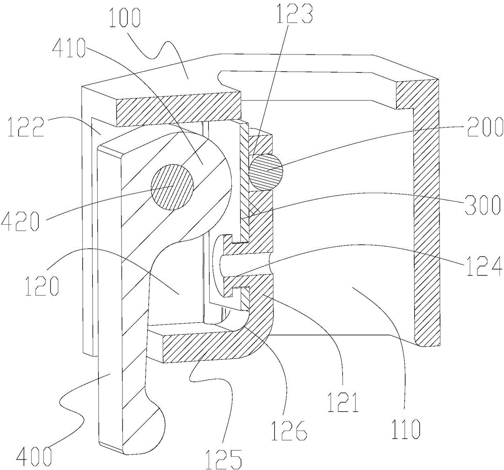
[0038] Such as figure 1 and figure 2 As shown, this embodiment proposes a stepped height locking device, including a locking seat 100 , a bead body 200 , a transmission block 300 and a cam handle 400 . combine image 3 and Figure 4 As shown, the locking seat 100 of this embodiment has an accommodating groove 120 and an installation through hole 110 for sheathing the handle bar. The groove bottom surface 121 of the accommodating groove 120 of this embodiment is arranged On the peripheral side, the notch 122 of the accommodating groove 120 is facing away from the bottom surface 121 of the groove and is open to the outside. like image 3 The shown conductive connection is on the peripheral side of the installation through hole 110, and the other end of the through hole 123 is conductively connected on the bottom surface 121 of the accommodating groove 120. The depth of the through hole 123 is less than the diameter of the bead body 200. The through hole 123 The aperture of...

Embodiment 2

[0045] Such as Figure 6 and Figure 7 As shown, the present embodiment proposes a self-balancing handle bar whose height can be adjusted in steps, including a locking device, a first bar 500 and a second bar 600, and the first bar 500 is inserted in the second bar 600, the locking device is arranged on the first rod 500 and the second rod 600, and is used to lock and fix the first rod 500 with different output lengths on the second rod 600 to form different overall high. Wherein, the locking device described in this embodiment adopts the stepped-height locking device described in Embodiment 1. For the specific structure of the stepped-height locking device, refer to the specific description of Embodiment 1 and its accompanying drawings. Here No longer.

[0046] to combine Figure 8 and Figure 9 As shown, a locking seat 100 is sleeved and fixed on the output port (not shown in the figure) of the second handle 600 for the output of the first handle 500, and the side of th...


PUM


Abstract

The invention discloses a step height locking device and a self-balancing handlebar rod with a height step adjustment function. The step height locking device comprises a locking seat, a ball, a transmission block and a cam handle. A cam portion of the cam handle is hinged to the wall of a containing groove, the transmission block is located between the bottom face of the groove and the cam portion, the transmission block slides towards a mounting through hole under the action of the cam portion of the cam handle, and then the ball is pushed to protrude into the mounting through hole. An output end opening of a second handlebar rod body of the self-balancing handlebar rod with the height step adjustment function is sleeved with the locking seat, the ball directly abuts against the peripheral side face of a first handlebar rod body through a gap, and a gear counter bore is formed in the peripheral side face of the first handlebar rod. The step height locking device and the self-balancing handlebar rod with the height step adjustment function are convenient to use, good in locking effect and long in service life, a user can carry out unlocking and locking operations through the cam handle, the damage degree of the ball is greatly reduced, and meanwhile the reliability of the linkage process is improved.

Description

technical field [0001] The invention relates to the technical field of locking mechanism design, in particular to a step-height locking device and a self-balancing handlebar with step-adjustable height. Background technique [0002] At present, in self-balancing two-wheeled vehicles, different users have different requirements for the height of the self-balancing handlebar. In order to realize the telescopic adjustment of the height of the handlebar, two sections of handlebars with different calibers are generally used for sheathing. , and use the locking device to lock and fix one rod to different positions on the other rod, so as to realize the telescopic adjustment of the overall height of the rod. However, the existing locking devices all have one or more of the following disadvantages: [0003] 1. The locking force is too large, the locking plate is severely worn, and the locking will fail after wearing. [0004] 2. The eccentricity of the locking needs to be adjusted...

Claims


Application Information

Patent Timeline
Patent Type & Authority Applications(China)
IPC IPC(8): B62K21/16
Inventor 沈林方继勇陈养彬
Owner NINGBO CHIKEWEI ELECTRONICS CO LTD
Learn More