


Quick Research
Generate reliable direction feasibility study reports for your R&D in just a few steps.

Technical Q&A
Discover and master advanced knowledge NOW. Basics, ideas, possibilities, all at once.

Find Solutions
As an expert in R&D theories, this can generate solutions to your technical problems instantly.

Evaluate Feasibility
Analyze your overall solution with one click, know your potential R&D risks in advance.

Monitor Landscape
Get weekly tech updates, stay abreast of the latest tech innovations and key insights.
Video coding method
A video encoding and encoding technology, applied in the field of encoding, can solve the problems of increasing the number of transistors, increasing the number of transistors and power consumption, complex compression algorithms, etc., achieving the effect of reducing the number of transistors, reducing device power consumption, and meeting the transmission bandwidth
- Summary
- Abstract
- Description
- Claims
- Application Information
AI Technical Summary
Problems solved by technology
Method used
Image

Examples
Embodiment 1
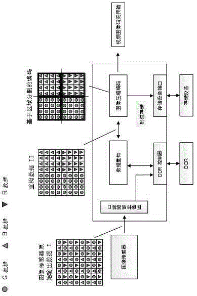
[0024] figure 1 It is shown that a specific embodiment of the present invention is a video coding method, including a coding process:
[0025] Firstly, the original output RAWRGB data I of the image sensor is obtained through the image sensor interface, and the data is buffered into DDR through the DDR interface. Through the data reconstruction module, the reconstruction data BLKRGB format II is established, and the reconstruction data format is as follows figure 1 The reconstructed data is shown in BLKRGB format II, where the small icon inside the diagram indicates the corresponding RGB number (eg: icon description).
[0026] In the interface, we also consider the different characteristics of R, G, and B, and design the ISP to improve the image quality and achieve the purpose of further compressing the code stream.
[0027] Then, the encoding module uses the reconstructed data in BLKRGB format II, and performs encoding based on region segmentation according to the correspon...
Embodiment 2
[0034] This example is basically the same as Example 1, the difference is:
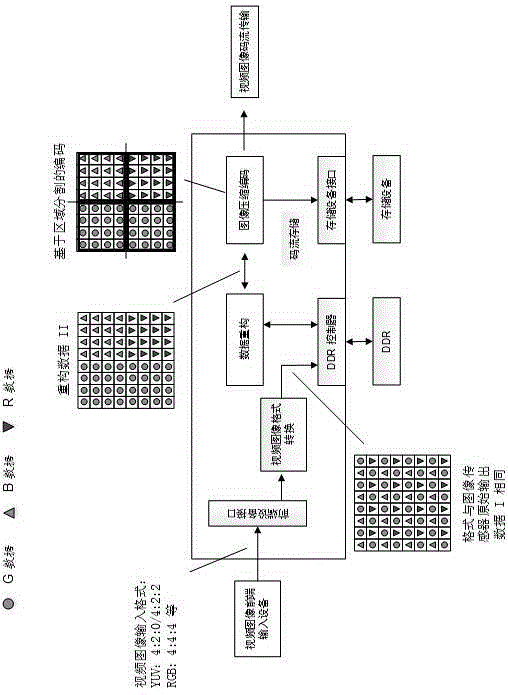
[0035] When using different video image input sources, depending on the input video image front-end equipment, there may be different video formats, such as YUV4:2:0 / 4:2:2, RGB4:4:4 format, etc. A video image format conversion module is added to the front end of the above-mentioned encoding method for format conversion, and the converted video image is directly encoded and decoded by the method described in this article. Its encoding implementation structure block diagram is as follows image 3 As shown, the decoding implementation structure block diagram is consistent with the process described in the example. The specific implementation steps are as follows.
[0036] Firstly, the input data of the video front-end input device is converted to the format described in this article (raw image sensor output data I) through the video image format conversion module, and the data is buffered into DDR thro...
example 2
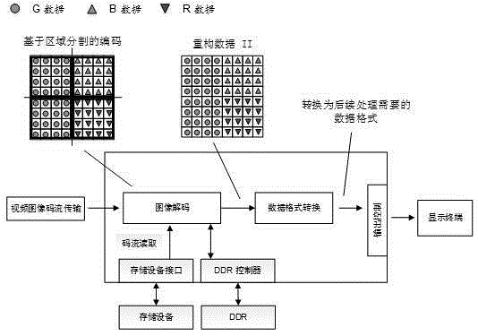
[0041] The decoding process of Example 2 is as follows Figure 4 It is shown that the decoding process of the decoding module is: the process of decoding and displaying is to restore the RAWRGB compressed code stream into an image.
[0042] First, the image code stream is transmitted from the network or locally to the decoding module. Through the decoding module, the region-segmented decoding is used to decode and reconstruct the reconstructed data in BLKRGB format II, and store it in DDR as a reference frame for subsequent decoding.
[0043] Secondly, the reconstructed data in BLKRGB format II is converted into data in the format required for subsequent processing through data format conversion, as data for subsequent processing or display.
[0044] Finally, the display module displays the converted image data according to different resolutions and presents them on the terminal.
[0045] This invention is an improvement scheme for the standard process of video image compress...
PUM
 Abstract
Description
Claims
Application Information
 - R&D Engineer
- R&D Manager
- IP Professional
- Industry Leading Data Capabilities
- Powerful AI technology
- Patent DNA Extraction
Browse by: Latest US Patents, China's latest patents, Technical Efficacy Thesaurus, Application Domain, Technology Topic, Popular Technical Reports.
© 2024 PatSnap. All rights reserved.Legal|Privacy policy|Modern Slavery Act Transparency Statement|Sitemap|About US| Contact US: help@patsnap.com