
Attaching plug with over-temperature alarm device

By installing a temperature sensor and an alarm indication circuit inside the power plug to monitor and alarm in real time, the problem of safety accidents caused by overheating of the plug is solved, and the effects of structural simplification, production cost reduction and accurate alarm are achieved.

Inactive Publication Date: 2016-02-03
DONG GUAN SONG WEI ELECTRIC TECH CO LTD
View PDF5 Cites 2 Cited by
  • Summary
  • Abstract
  • Description
  • Claims
  • Application Information

AI Technical Summary

Problems solved by technology

[0002] The power plug is widely used in various fields. It is usually adapted to the power socket to achieve electrical connection. In terms of power supply, the power plug plays an important role as a bridge. In practical applications, it is easy to appear poor contact at the plug. When When the plug is in poor contact, its resistance will gradually increase, and the temperature will gradually increase. In severe cases, the plug will be overheated and damaged or even ignited. If it is not found in time, it may turn into a safety accident. temperature, so that problems can be detected as early as possible, and faults can be eliminated in time to prevent safety accidents
[0003] In the prior art, there are also some technical solutions for preventing overheating of power plugs, but they generally have some defects, such as: complex structure and production process, high production cost, inconvenient installation and maintenance, and easy deviation of measurement results, etc.

Method used


Image

  • Attaching plug with over-temperature alarm device
  • Attaching plug with over-temperature alarm device
  • Attaching plug with over-temperature alarm device

Examples


Embodiment Construction

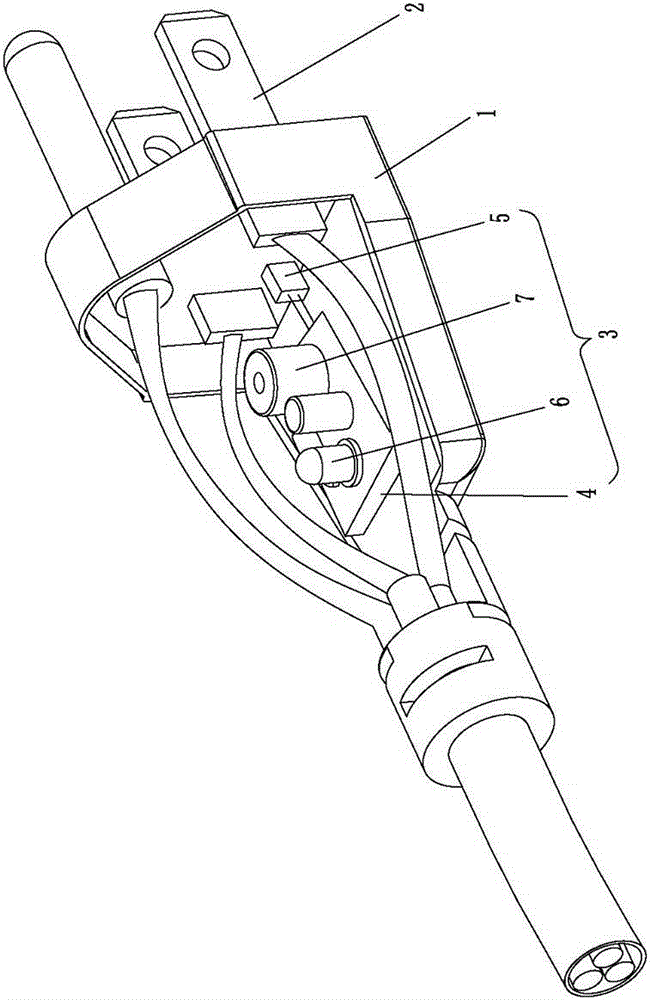
[0034] Please refer to Figure 1 to Figure 3 As shown, it shows the specific structure of the embodiment of the present invention, which includes a plug base body 1, a pin 2 and an overheat alarm device 3, and the pin 2 protrudes from the plug base body 1 to the outside in front of the plug base body 1. On the other hand, the overheat alarm device 3 is arranged inside the socket body 1 of the plug; usually, there are more than two pins 2 of the power plug, that is, the power plug can be a two-pin, three-pin or more pin-type plug.

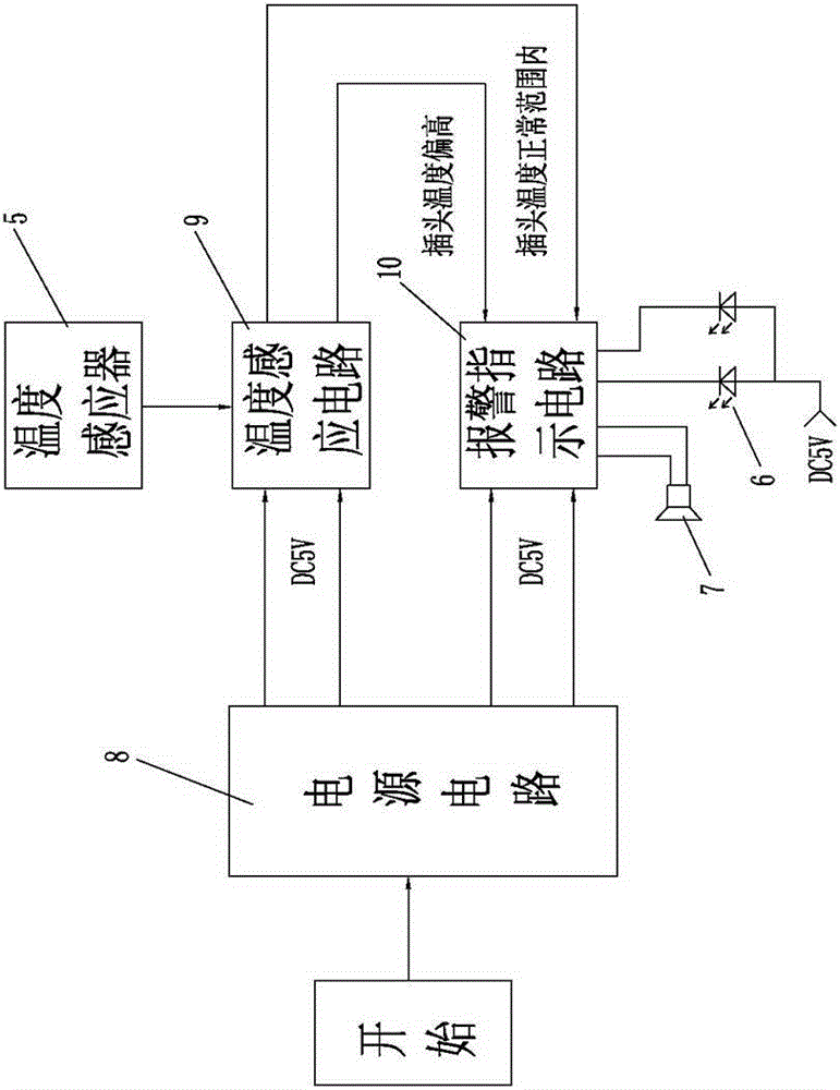
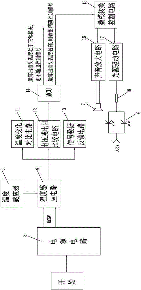
[0035] The overheat alarm device 3 includes an alarm indication control panel 4, a temperature sensor 5 connected to the alarm indication control panel 4, and an alarm unit; the alarm indication control panel 4 is provided with a power supply circuit 8, a temperature sensing circuit 9 and an alarm indication circuit 10, wherein, the temperature sensor 5 is welded on the alarm indication control board 4 in a direct-insertion or patch type manner; the...


PUM


Abstract

The invention discloses an attaching plug with an over-temperature alarm device. The attaching plug comprises a plug seat body, a plug pin and the over-temperature alarm device, wherein the plug pin convexly extends out of the front side of the plug seat body from the plug seat body from inside to outside; the over-temperature alarm device is arranged in the plug seat body and comprises an alarm indication control board, a temperature inductor and an alarm unit; a power supply circuit, a temperature induction circuit and an alarm indication circuit are arranged on the alarm indication control board, so that the temperature in the plug seat body is induced through the temperature inductor to correspondingly change a resistance value generated by a temperature change; a resistance value signal generated by the temperature inductor is transmitted to the temperature induction circuit and is transmitted to the alarm indication circuit to drive the alarm unit to carry out a real-time alarm and to prevent a fire. Particularly, the structure and the production technology of the attaching plug are simple; the over-temperature alarm device is directly arranged in the traditional plug; the supplied electricity is directly taken from the inside of the plug; and the attaching plug is applicable to promotion, production and application.

Description

technical field [0001] The invention relates to the technology in the field of power plugs, in particular to a power plug with an overheat alarm device. Background technique [0002] Power plugs are widely used in various fields. They are usually adapted to power sockets to achieve electrical connection. In terms of power supply, power plugs play an important role as a bridge. In practical applications, poor contact at the plug is prone to occur. When When the contact of the plug is poor, its resistance gradually increases, and the temperature gradually increases. In severe cases, the plug will be overheated and damaged or even caught on fire. If it is not detected in time, it is likely to evolve into a safety accident. Therefore, it is necessary to monitor the plug in real time. temperature, so that problems can be detected as early as possible, and faults can be eliminated in time to prevent the occurrence of safety accidents. [0003] In the prior art, some technical sol...

Claims


Application Information

Patent Timeline
Patent Type & Authority Applications(China)
IPC IPC(8): H01R13/66H01R13/717G01K7/16
CPCH01R24/30H01R13/6683H01R2103/00H01R13/6666H01R13/6691H01R13/7175H01R24/28
Inventor 吕威霖
Owner DONG GUAN SONG WEI ELECTRIC TECH CO LTD
Learn More