
Telephoto type super-large image plane high definition lens and installation method thereof

A telephoto and lens technology, applied in optical components, optics, instruments, etc., can solve the problems of increased design difficulty, difficult ratio, difficult application, etc., to achieve enhanced optical information collection capabilities, overcome serious front-to-back separation, and high-resolution Effect

Active Publication Date: 2016-02-03
FUJIAN FORECAM OPTICS CO LTD
View PDF5 Cites 8 Cited by
  • Summary
  • Abstract
  • Description
  • Claims
  • Application Information

AI Technical Summary

Problems solved by technology

However, this system also has inherent disadvantages. For example, the main focal power of the system is concentrated in the front part of the system, which increases the difficulty of correcting axial aberrations such as spherical aberration, chromatic aberration, and especially secondary spectrum; Off-axis aberrations, especially vertical axis chromatic aberration, distortion, etc. severely limit the field of view of telephoto systems, making it difficult to apply in systems with large target surfaces; when a large amount of light is required, the ratio of the total optical length to the focal length of the system is also difficult to improve. The ratio of the general telephoto refraction system is about 0.75~0.85; especially when this type of system is required to be adapted to a high-definition camera, the design difficulty is increased

Method used


Image

  • Telephoto type super-large image plane high definition lens and installation method thereof
  • Telephoto type super-large image plane high definition lens and installation method thereof

Examples


Embodiment Construction

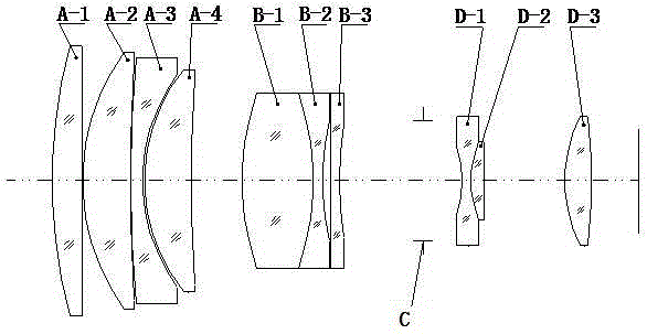
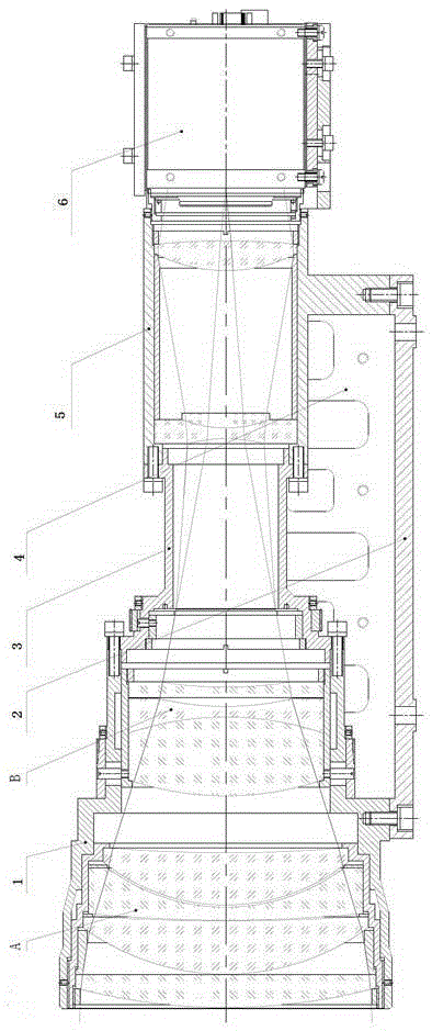
[0022] Such as Figure 1~2 As shown, a telephoto ultra-large image surface high-definition lens is characterized in that: the mechanical structure of the lens includes a main lens barrel, a rear group lens barrel, and a CCD assembly that are sequentially installed and connected to the base plate from left to right. The main lens barrel and the rear group of lens barrels are connected through a diaphragm seat. The optical system of the lens includes a front fixed group A with a positive refractive power and a focal power of Negative focusing group B, iris C, and rear fixed group D with positive refractive power, the front fixed group A and focusing group B are arranged in the main lens barrel, and the rear fixed group D is arranged in Inside the rear lens barrel.

[0023] In this embodiment, the front fixed group A includes a plano-convex lens A-1, a positive crescent lens A-2, a negative crescent lens A-3, and a positive crescent lens A-4 arranged in sequence. B includes a f...


PUM


Abstract

The invention relates to a telephoto type super-large image plane high definition lens and an installation method thereof. The mechanical structure of the lens comprises a main lens barrel, a rear lens barrel and a CCD assembly, which are sequentially disposed on a base plate from left to right. The main lens barrel and the rear lens barrel are connected via a diaphragm stand. An optical system of the lens comprises a front fixed unit A with positive focal power focal, a focusing unit B with negative focal power, a variable diaphragm C and a rear fixed unit D with positive focal power, which are disposed along an optical path in an incident direction from left to right. The front fixed unit A and the focusing unit B are disposed in the main lens barrel, and the rear fixed unit D is disposed in the rear lens barrel. The ratio of the optical overall length of the lens to the system focal length is less than 0.56, and is far smaller than that of a general telephoto type refraction system. The telephoto type super-large image plane high definition lens overcomes the disadvantages that a telephoto type structure has off axis aberration that is difficult to correct and cannot adapt to large target surface imaging. The imaging target surface of the lens reaches 44mm, so the optical information collection capability of the lens is substantially enhances. The lens has the characteristics of large light quantity and high resolution, and can match a high-definition camera.

Description

technical field [0001] The invention relates to a telephoto ultra-large image surface high-definition lens and an installation method thereof, belonging to the field of optoelectronic technology. Background technique [0002] Due to its unique compact structure, telephoto optical system has been widely used in occasions that impose strict geometrical restrictions on the system. However, this system also has inherent disadvantages. For example, the main focal power of the system is concentrated in the front part of the system, which increases the difficulty of correcting axial aberrations such as spherical aberration, chromatic aberration, and especially secondary spectrum; Off-axis aberrations, especially vertical axis chromatic aberration, distortion, etc. severely limit the field of view of telephoto systems, making it difficult to apply in systems with large target surfaces; when a large amount of light is required, the ratio of the total optical length to the focal lengt...

Claims


Application Information

Patent Timeline
Patent Type & Authority Applications(China)
IPC IPC(8): G02B13/02G02B13/00
CPCG02B13/0045G02B13/02
Inventor 屈立辉陈鹏刘辉周宝藏张清苏
Owner FUJIAN FORECAM OPTICS CO LTD
Learn More