
A simulation test device for dislocation of weak structural belts under stress

A stress action and simulation test technology, applied in the direction of using mechanical devices, measuring devices, instruments, etc., can solve problems such as large differences, difficulty in simulating three-dimensional stress states, and difficult conclusions to explain problems, so as to avoid uneven radial stress. Effect

Active Publication Date: 2017-12-05
INST OF ROCK & SOIL MECHANICS CHINESE ACAD OF SCI
View PDF8 Cites 0 Cited by
  • Summary
  • Abstract
  • Description
  • Claims
  • Application Information

AI Technical Summary

Problems solved by technology

[0005] 1) The sliding of active fault zones is mostly simulated by shear tests, and most shear test equipment can only apply one-way or two-way stress to the sample, and it is difficult to simulate the three-way stress state;
[0006] 2) Most of the model samples are composed of two parts, ignoring the composition characteristics of the three parts of the active fault zone (upper, lower wall and middle weak structure)
[0007] 3) After the initial stress is applied to the model test equipment, the tunnel / hole cannot be excavated, so the excavation effect of the model sample cannot be simulated, and the deformation characteristics and stress redistribution of the tunnel after excavation cannot be known.
However, the force state of the pre-excavated samples with holes is far from that of the on-site engineering, and the conclusions drawn are difficult to explain the problem.
[0008] Due to the lack of test devices that can reasonably simulate the dislocation simulation of weak structural belts under the action of stress, the relevant research work is mainly carried out through numerical simulation and theoretical analysis, and the results obtained are quite different from the actual situation in the field.

Method used


Image

  • A simulation test device for dislocation of weak structural belts under stress
  • A simulation test device for dislocation of weak structural belts under stress
  • A simulation test device for dislocation of weak structural belts under stress

Examples


Embodiment Construction

[0032] The principles and features of the present invention are described below in conjunction with the accompanying drawings, and the examples given are only used to explain the present invention, and are not intended to limit the scope of the present invention.

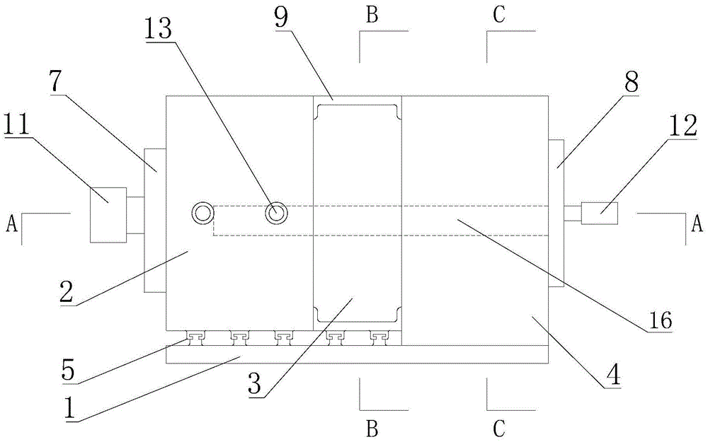
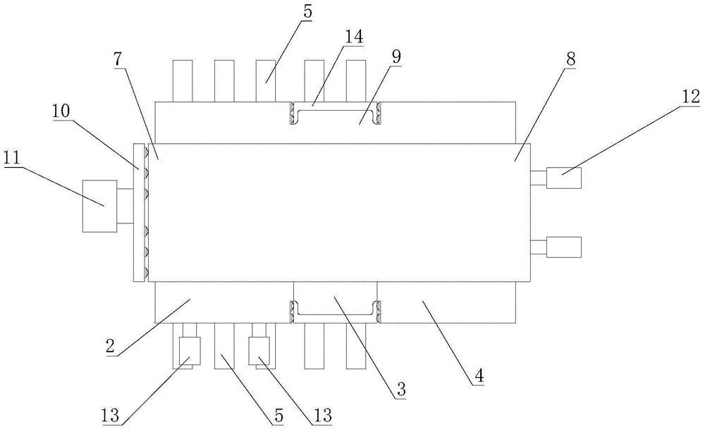
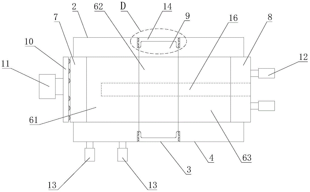
[0033] Such as Figure 1-5 As shown, a kind of simulation test device for the dislocation of weak structural belts under the action of stress includes a base 1 on which a left sample chamber 2, a dislocation chamber 3 and a right sample chamber 4 are sequentially arranged, and the left sample chamber 2 The left sample chamber 2, the shift chamber 3, and the right sample chamber 4 are all rectangular columns, and the three are respectively provided with left through holes for placing samples. 61. The middle through hole 62 and the right through hole 63, the above three through holes are equidiameter cylindrical through holes, sliding the left sample chamber 2 and the shift chamber 3 along the guide rail 5 can make th...


PUM


Abstract

The invention relates to a weak structural belt diastrophism simulation test device under stress action. The device comprises a base, a left sample chamber, a diastrophism chamber and a right sample chamber are sequentially arranged on the base, the left sample chamber and the diastrophism chamber are connected with the base through a guide rail in a sliding mode, and the left sample chamber, the diastrophism chamber and the right sample chamber are all rectangular columns and internally provided with coaxial equal-diameter cylindrical through holes. The ends, close to the left sample chamber, of the through holes are provided with a left cushion block, and the ends, close to the right sample chamber, of the through holes are provided with a right cushion block. The diastrophism chamber comprises an outer limiting plate and an annular water bag arranged on the inner surface of the outer limiting plate. The inner diameter of the annular water bag is equal to the radius of the through holes. A first loading device is arranged on the side, far away from the left sample chamber, of the left cushion block. A second loading device is arranged at the end, far away from the right sample chamber, of the right cushion block. The other side of the left sample chamber is further provided with a third loading device driving the left sample chamber to move along the guide rail. The weak structural belt diastrophism simulation test device has the advantages of being simple in structure, capable of simulating three-direction stress and uniform in force application.

Description

technical field [0001] The invention relates to the technical field of rock mass mechanics model test equipment, in particular to a device for simulating the movement of a weak structural zone under stress. Background technique [0002] With the rapid development of my country's transportation and water conservancy undertakings, the demand and importance of tunnel / cavity construction have become increasingly apparent. The geological conditions in western my country are complex, with frequent fault activities and different characters. Therefore, in the process of route selection, tunnels often inevitably cross the fracture zone. The fracture zone of the tunnel fault has the characteristics of poor geological conditions of the surrounding rock and the transition from soft rock to hard rock or from hard rock to soft rock. Earthquake and "5.12" Wenchuan Earthquake and other tunnel earthquake damages have proved this rule. The impact of active faults on engineering is mainly m...

Claims


Application Information

Patent Timeline
Patent Type & Authority Patents(China)
IPC IPC(8): G01N19/00
Inventor 张传庆崔国建周辉朱国金赵阳沈峥
Owner INST OF ROCK & SOIL MECHANICS CHINESE ACAD OF SCI
Learn More