
Dynamic and static pressure bearing circular tooth gear oil pump

A circular arc gear, dynamic and static pressure technology, applied in the direction of pumps, rotary piston type/swing piston type pump components, lubrication pumps, etc., can solve the problems of large axial and radial unbalanced force, large leakage, oil trapped in the oil pump, etc. Achieve the effect of solving low-speed wear, long service life and reducing leakage

Inactive Publication Date: 2016-02-03
CENT RES INST OF TIANJIN BENEFO MECHANICAL EQUIP GRP CO LTD
View PDF7 Cites 5 Cited by
  • Summary
  • Abstract
  • Description
  • Claims
  • Application Information

AI Technical Summary

Problems solved by technology

[0005] In order to solve the technical problems existing in the known technology, the present invention provides a dynamic and static pressure bearing circular arc gear oil pump. By optimizing the structural design and oil passage layout, the oil pump can solve the problems of oil trapping, large leakage, and large axial and radial unbalanced forces. Make the load distribution and stress condition more reasonable, improve the service life and reliability of the equipment, make the equipment compact, good rigidity, large output torque, low cost, convenient maintenance, reliable sealing, and improve the maintainability and performance of the equipment

Method used


Image

  • Dynamic and static pressure bearing circular tooth gear oil pump
  • Dynamic and static pressure bearing circular tooth gear oil pump
  • Dynamic and static pressure bearing circular tooth gear oil pump

Examples


Embodiment Construction

[0019] In order to further understand the content of the invention, characteristics and effects of the present invention, the following examples are described in detail as follows:

[0020] The arc gear pump is a rotary pump that relies on the change and movement of the working volume formed between the pump cylinder and the meshing gear to deliver liquid or pressurize it. When the gear of the arc gear pump rotates, the volume of the space on the side where the gear is disengaged becomes larger, forming a vacuum to suck the liquid, and the volume of the space on the meshing side of the gear changes from large to small, and the liquid is squeezed into the pipeline. The suction chamber and the discharge chamber are separated by the meshing line of two arc gears. The resistance at the outlet of the gear oil pump forms the delivery pressure of the oil pump.

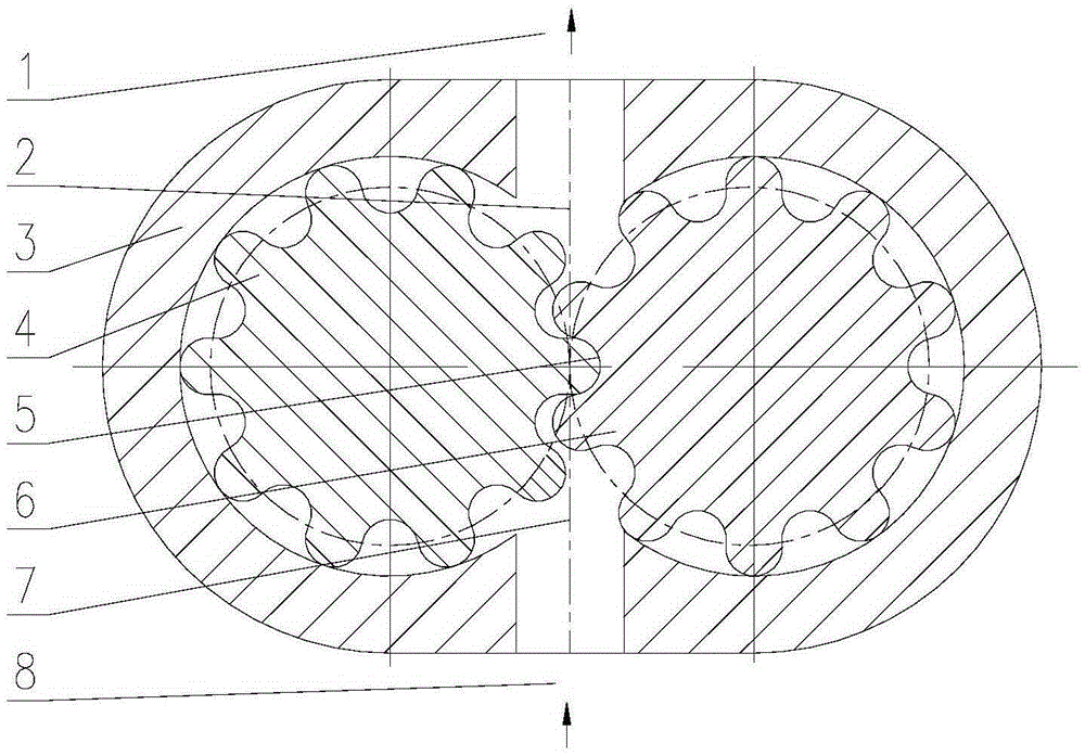
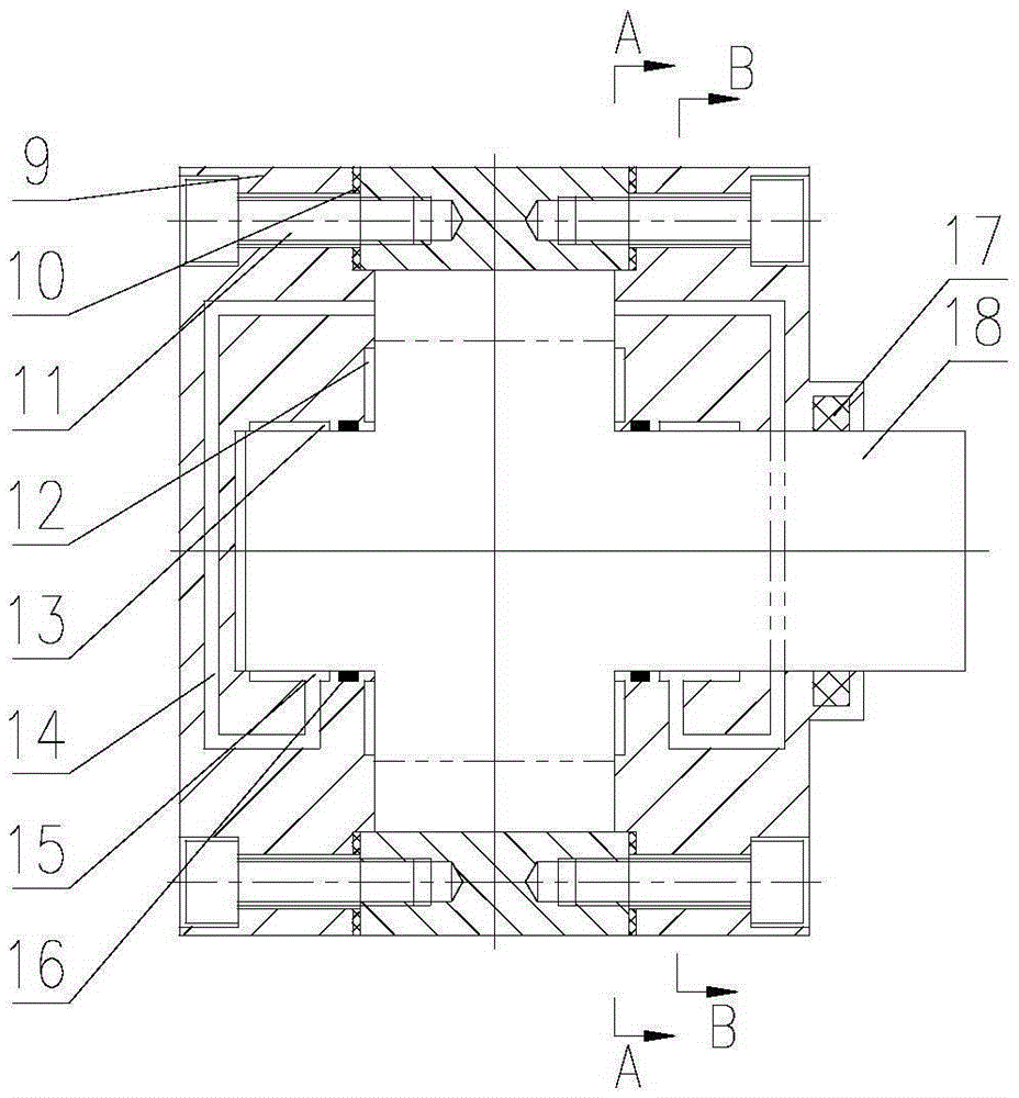
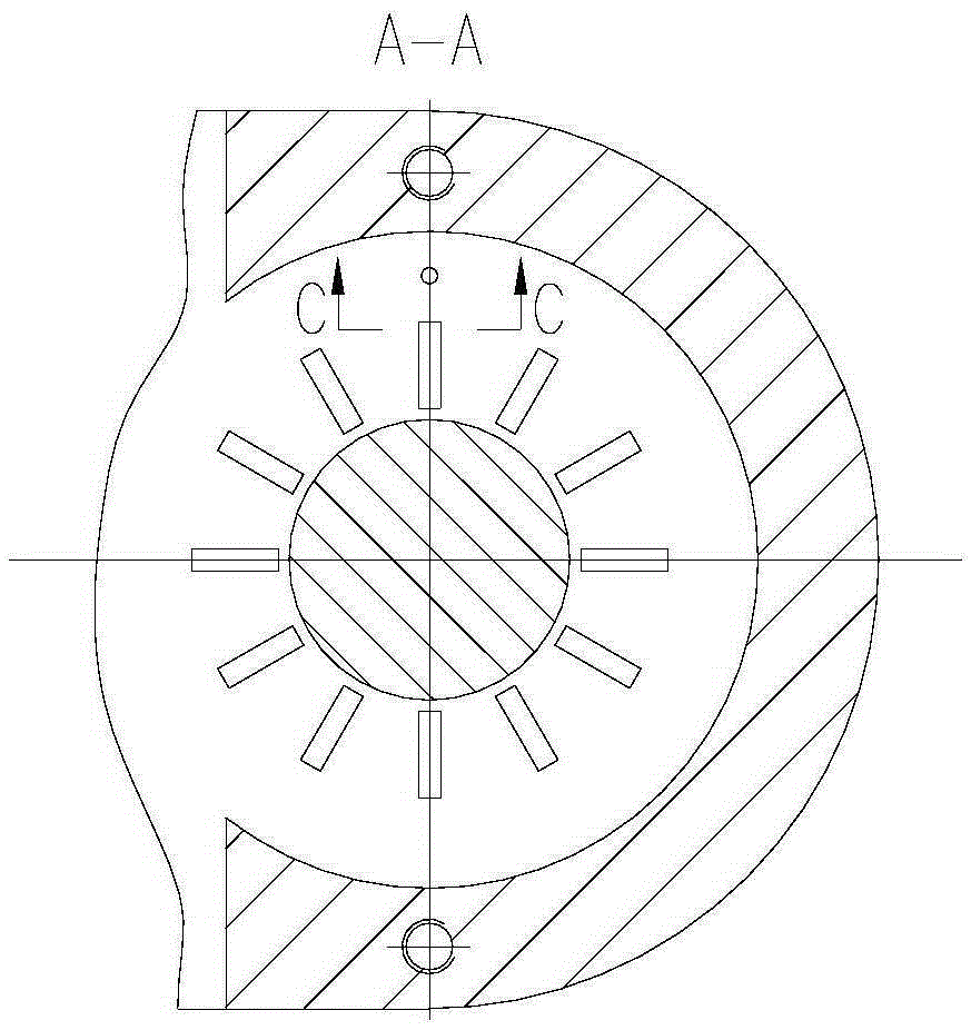
[0021] See Figure 1 to Figure 3 The gear oil pump of the present invention includes a pump body 3 with an active arc gea...


PUM


Abstract

The invention relates to a dynamic and static pressure bearing circular tooth gear oil pump. A dynamic pressure bearing for bearing a gear shaft of a driving circular arc gear and a gear shaft of a driven circular arc gear is arranged on the inner side of a pump cover. The dynamic pressure bearing comprises a gear shaft hole formed in the inner end face of the pump cover. A plurality of shaft side dynamic pressure grooves extending in the axial direction are formed in the inner wall of the gear shaft hole in the circumferential direction, wherein the shaft side dynamic pressure grooves in one side of a low-pressure cavity form a static pressure balance groove. An oil way is further formed inside the pump cover, one end of the oil way penetrates a high pressure cavity, and the other end of the oil way penetrates the static pressure balance groove. Supporting rings are arranged between the inner wall of the gear shaft hole and shaft shoulders of the gear shafts of the driving circular arc gear and the driven circular arc gear. A plurality of wheel side dynamic pressure grooves extending in the radial direction are formed in the inner end face of the pump cover in the circumferential direction of the outer side of the gear shaft hole. The wheel side dynamic pressure grooves in the two sides of the driving circular arc gear and the driven circular arc gear are symmetric and provide the axial force in the same magnitude and opposite directions.

Description

technical field [0001] The invention belongs to the technical field of oil pumps, in particular to a dynamic and static pressure bearing arc gear oil pump. Background technique [0002] Gear oil pumps have problems such as unbalanced radial force, high noise, and low efficiency when transporting various lubricating liquids. When the hydraulic oil is running in the involute gear pump, the closed volume at the intersection of the gears changes with time, and a part of the hydraulic oil is trapped between the teeth, resulting in vibration and noise. Setting unloading grooves on the front and rear cover plates or floating bushings can solve the problem to a certain extent, but it is impossible to open the middle of the unloading grooves, so there is always a distance in the middle where there is a slight oil trapped phenomenon. The separation distance between the unloading groove connected with the oil inlet and the unloaded groove connected with the oil outlet is very short, t...

Claims


Application Information

Patent Timeline
Patent Type & Authority Applications(China)
IPC IPC(8): F04C2/18F16N13/20F04C15/00
Inventor 左斌黄威
Owner CENT RES INST OF TIANJIN BENEFO MECHANICAL EQUIP GRP CO LTD
Learn More