Bus protection method based on line mode current S transformation argument detection
A line-mode current and busbar protection technology, applied in the direction of the fault location, can solve the problems of current transformer saturation and transition resistance, and achieve the effect of low sampling rate and simple principle
- Summary
- Abstract
- Description
- Claims
- Application Information
AI Technical Summary
Problems solved by technology
Method used
Image


Examples
Embodiment 1
[0036] Example 1: Bus fault
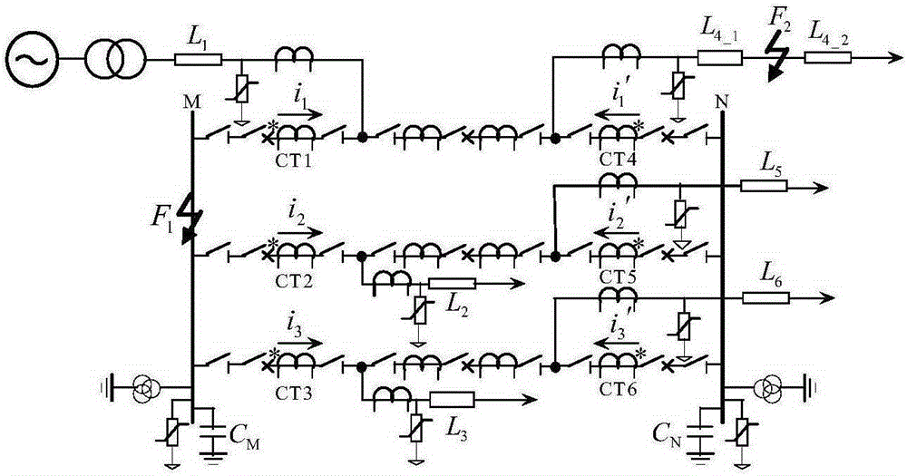
[0037] by figure 1 The power transmission system shown is taken as an example, and its line parameters are set as follows: the system bus adopts 3 / 2 connection, and the length of each outgoing line connected to the bus is L 1 =L 2 =L 3 =L 4 = 400km. Fault setting: set the phase A ground fault on the busbar, the initial phase angle of the fault is 90°, the transition resistance is 10Ω, the sampling rate is 10kHz, the fault time is set to 0.4463s, and the time range is 0.4453s to 0.4473s for fault three phase current.
[0038] (1) According to the set fault, get the three-phase current data through the measuring terminal according to step 1 in the manual, and calculate the line-mode current data including the fault phase;
[0039] (2) Carry out S-transformation to the line-mode current containing the fault phase according to step 2 to obtain an amplitude matrix, and determine the arrival time of the traveling wave by the abrupt point of the hi...
Embodiment 2
[0042] Example 2: Line L 1 Fault
[0043] by figure 1 The power transmission system shown is taken as an example, and its line parameters are set as follows: the system bus adopts 3 / 2 connection, and the length of each outgoing line connected to the bus is L 1 =L 2 =L 3 =L 4 = 400km. Fault setting: set line L 1 When a phase A ground fault occurs, the initial phase angle of the fault is 90°, the transition resistance is 10Ω, the sampling rate is 10kHz, the fault time is set to 0.4463s, and the fault three-phase current is taken within the time interval from 0.4453s to 0.4473s.
[0044](1) According to the set fault, get the three-phase current data through the measuring terminal according to step 1 in the manual, and calculate the line-mode current data including the fault phase;
[0045] (2) Carry out S-transformation to the line-mode current containing the fault phase according to step 2 to obtain an amplitude matrix, and determine the arrival time of the traveling wav...
Embodiment 3
[0048] Example 3: Line L 2 Fault
[0049] by figure 1 The power transmission system shown is taken as an example, and its line parameters are set as follows: the system bus adopts 3 / 2 connection, and the length of each outgoing line connected to the bus is L 1 =L 2 =L 3 =L 4 = 400km. Fault setting: set line L 2 When a phase A ground fault occurs, the initial phase angle of the fault is 90°, the transition resistance is 10Ω, the sampling rate is 10kHz, the fault time is set to 0.4463s, and the fault three-phase current is taken within the time interval from 0.4453s to 0.4473s.
[0050] (1) According to the set fault, get the three-phase current data through the measuring terminal according to step 1 in the manual, and calculate the line-mode current data including the fault phase;
[0051] (2) Carry out S-transformation to the line-mode current containing the fault phase according to step 2 to obtain an amplitude matrix, and determine the arrival time of the traveling wa...
PUM
 Abstract
Description
Claims
Application Information
 - R&D
- Intellectual Property
- Life Sciences
- Materials
- Tech Scout
- Unparalleled Data Quality
- Higher Quality Content
- 60% Fewer Hallucinations
Browse by: Latest US Patents, China's latest patents, Technical Efficacy Thesaurus, Application Domain, Technology Topic, Popular Technical Reports.
© 2025 PatSnap. All rights reserved.Legal|Privacy policy|Modern Slavery Act Transparency Statement|Sitemap|About US| Contact US: help@patsnap.com