Ship wave power generation stabilizing unit and wave power generation system
A technology of wave power generation and anti-rolling device, which is applied in the field of ships and can solve problems such as consumption
- Summary
- Abstract
- Description
- Claims
- Application Information
AI Technical Summary
Problems solved by technology
Method used
Image
Examples
Embodiment 1
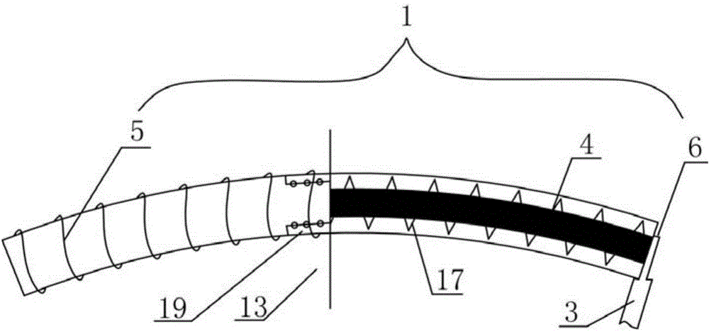
[0045] Such as figure 1 As shown, the ship wave power generation anti-rolling device provided in this embodiment includes a ship wave power generating mechanism and a ship side wave receiving force applying mechanism that provides power for the ship wave generating mechanism, and the ship side wave receiving force applying mechanism includes a The energy conversion movable wall 3 is connected, and the energy conversion movable wall 3 can generate mechanical motion under the action of wave force; the ship wave power generation mechanism generates electric energy under the drive of the energy conversion movable wall 3, which is used to supply power to the ship.
[0046] When the ship is sailing at sea, the wave force causes the hull to sway with the largest roll amplitude in the 13 six degrees of freedom, and the wave energy that pushes the huge ship to roll continuously can be converted into electrical energy by the ship's wave power generation anti-rolling device to realize shi...
Embodiment 2
[0064] Such as figure 1 and Figure 5-6 As shown, the ship wave power generation anti-rolling device provided in this embodiment includes a ship wave power generating mechanism and a ship side wave receiving force applying mechanism that provides power for the ship wave generating mechanism, and the ship side wave receiving force applying mechanism includes a The energy conversion movable wall 3 is connected, and the energy conversion movable wall 3 can generate mechanical motion under the action of wave force, and the ship wave power generation mechanism generates electric energy under the drive of the energy conversion movable wall 3 .
[0065]The wave power generation mechanism includes a wind box wind channel power generation device 2, and the wind box wind channel power generation device 2 includes a wind box 10, an air channel 7, an impeller 8 and a generator 9; Between, the top of the bellows 10 is connected between the energy conversion movable wall 3 and the hull 13 ...
Embodiment 3
[0074] The ship wave power generation and anti-rolling device provided in this embodiment includes a ship wave power generation mechanism and a ship side wave receiving force mechanism that provides power for the ship wave power generation mechanism. The movable wall 3, the energy conversion movable wall 3 can generate mechanical motion under the action of wave force, and the ship wave power generation mechanism generates electric energy driven by the energy conversion movable wall 3.
[0075] The marine wave power generating mechanism includes a moving magnetic bar power generating device 1 and a wind box air duct power generating device 2 .
[0076] Wherein, the moving bar magnet generating device 1 comprises a bar magnet 4, a solenoid 5, and a force arm 6; The top, the other end of which faces the solenoid 5, and is driven by the force arm 6 to reciprocate through the solenoid 5; the solenoid 5 is composed of metal wire windings; the force arm 6 is located at the top of the...
PUM
 Abstract
Description
Claims
Application Information
 - R&D
- Intellectual Property
- Life Sciences
- Materials
- Tech Scout
- Unparalleled Data Quality
- Higher Quality Content
- 60% Fewer Hallucinations
Browse by: Latest US Patents, China's latest patents, Technical Efficacy Thesaurus, Application Domain, Technology Topic, Popular Technical Reports.
© 2025 PatSnap. All rights reserved.Legal|Privacy policy|Modern Slavery Act Transparency Statement|Sitemap|About US| Contact US: help@patsnap.com


