Eureka AIR delivers breakthrough ideas for toughest innovation challenges, trusted by R&D personnel around the world.

Automatic control door

A pneumatic control system, a technology for moving doors, applied in the field of new technology applications, can solve the problems of mechanical doors not having a visual function, inconvenient opening and closing of doors, poor sealing effect, etc. The combined structure is compact and the sound insulation effect is obvious.

Inactive Publication Date: 2016-01-27
玉溪市新特科技有限公司
View PDF6 Cites 3 Cited by
  • Summary
  • Abstract
  • Description
  • Claims
  • Application Information

AI Technical Summary

Problems solved by technology

Today's mechanical equipment has a high degree of automation, but some mechanical doors are still very simple and noisy, which requires a door that can automatically reduce noise to cooperate with the operation of advanced machines to achieve high efficiency and environmental protection
[0003] At present, the door frames of many machines are relatively heavy, and the mechanical doors of some mechanical equipment have no visual function. The doors are inconvenient to open and close, the sealing effect is not good, and the noise reduction ability is poor. work efficiency

Method used


Image

  • Automatic control door
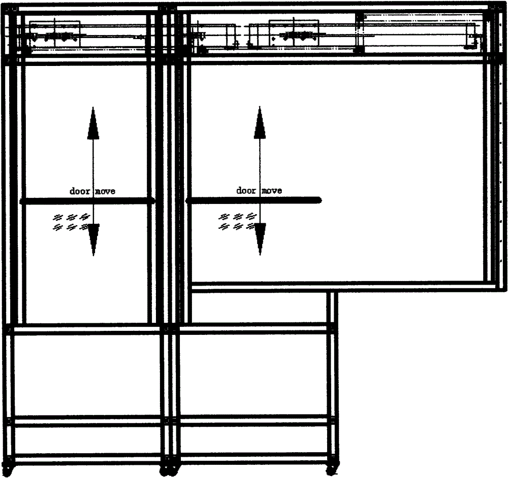
  • Automatic control door
  • Automatic control door

Examples


Embodiment Construction

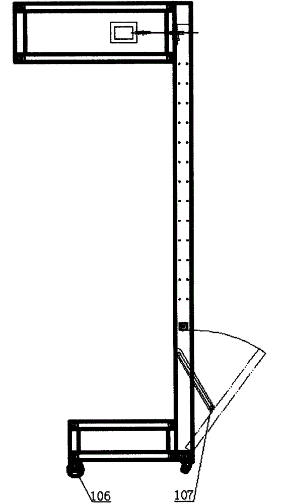
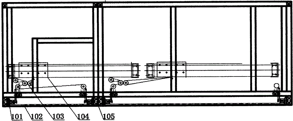
[0022] The following will be combined with Figure 6 The present invention will be described in further detail.

[0023] An automatic control door includes three parts: a lifting mechanism, an electric control structure and a lower layer.

[0024] Lifting mechanism 109 is installed in the rear of both sides of GD movable door, and its structure is as follows: Figure 6 As shown, it includes 7603 industrial super heavy-duty three-section ball guide rail 101, galvanized steel wire rope 204 for connecting function and pulley block 103 for auxiliary function. The three-section ball guide rail is installed on both sides of the GD sliding door, which is used to stabilize the GD sliding door and guide it to move up and down. The wire rope is used to connect the GD movable door and the load cell 201 of the electrical control system. The pulley group is strung on the wire rope to realize the stable lifting of the GD sliding door. During use, the GD moves the door handle up and down...


PUM


Abstract

The invention discloses an automatic control door. The automatic control door comprises a door frame structure and an electric control part. Equipment doors are transformed based on the conditions that the mechanical doors of certain mechanical equipment do not have a visual function, the doors are inconvenient to open and close, and the sound insulation and noise reduction ability is poor. The overall structure of the automatic control door serving as a mechanical protective door matched with the mechanical equipment is made of an aluminum profile, so that the whole is light and operation staff can conveniently open or close the automatic control door. Work staff watch the operation conditions of the equipment through organic glass on the door. The automatic control door is connected with the machine body of the used equipment, and sound insulation and noise reduction are conducted on the equipment on every side. The automatic control door can move up and down when being pulled and stop freely, so that not only can the surrounding work staff be effectively protected, but also the equipment is convenient to operate and maintain.

Description

technical field [0001] The invention relates to the field of new technology application. By adopting the electric automatic control and sealing technology, the door of the mechanical equipment can be sound-proofed and noise-reduced, and can be pulled up and down freely and stopped, which is convenient for equipment operation and maintenance. Background technique [0002] With the continuous development and growth of the machinery industry, the machinery and equipment are becoming more and more advanced, and people are developing in the direction of high efficiency, energy saving, and environmental protection. Various automated machines are emerging. The machine door serves as a bridge between people and machines. also plays a huge role. Today's mechanical equipment has a high degree of automation, but some mechanical doors are still very simple and noisy, which requires a door that can automatically reduce noise to cooperate with the operation of advanced machines to achieve...

Claims


Application Information

Patent Timeline
IPC IPC(8): E05F15/04E05F15/08E05F15/20E06B3/12E05D13/00E06B7/22E06B5/20
Inventor 李新亮
Owner 玉溪市新特科技有限公司
Why Eureka
Eureka Blog
Learn More