
Annular bar rotating and clamping device

A rotary clamp and ring-shaped technology, which is applied in the field of circular rotary clamping devices for bar materials, can solve problems such as effective clamping of difficult bar materials, hand burns, and people's inability to grasp with bare hands, achieving the effect of high degree of automation and convenient operation

Inactive Publication Date: 2016-01-27
WUHU TAINENG ELECTRIC APPLIANCES
View PDF4 Cites 7 Cited by
  • Summary
  • Abstract
  • Description
  • Claims
  • Application Information

AI Technical Summary

Problems solved by technology

[0002] Generally speaking, the temperature of the heated bar is too high for people to grab it with bare hands. Although the long-handled clamp can be used for manual auxiliary clamping, the long-handled clamp has better thermal conductivity and the temperature of the bar Too high, even if people use long-handled clamps to grip, they will cause some burns to the hands. Therefore, most processing workshops have begun to introduce robot arms to grab the bar, but because the surface of the bar is relatively smooth, It is difficult for the equipment installed at the end of the robot arm to effectively grip the bar

Method used


Image

  • Annular bar rotating and clamping device
  • Annular bar rotating and clamping device
  • Annular bar rotating and clamping device

Examples


Embodiment Construction

[0014] In order to make the technical means, creative features, goals and effects achieved by the present invention easy to understand, the present invention will be further elaborated below.

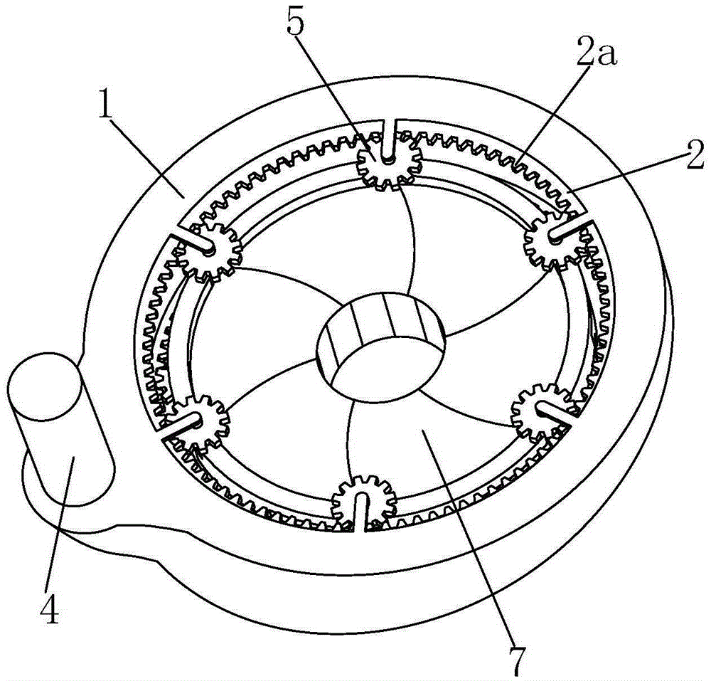
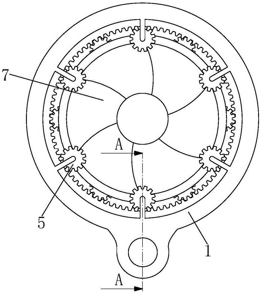
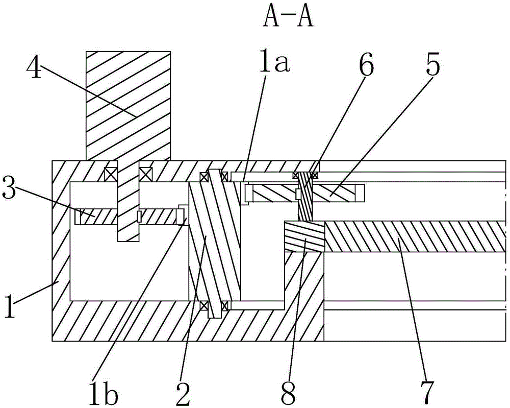
[0015] like Figure 1 to Figure 3 As shown, a ring-shaped rotary clamping device for bar material mainly includes a ring-shaped sleeve frame 1, and an annular swivel frame 2 is mounted on the inside of the sleeve frame 1, and the swivel frame 2 is respectively equipped with The inner ring gear 1a and the outer ring gear 1b, the outer ring gear 1b is meshed with a transmission gear 3, and the transmission gear 3 is connected with a motor 4.

[0016] The inner ring gear 1a is meshed with six pinions 5 distributed in a ring, and the pinions 5 are connected to a rotating shaft 6, and the lower ends of the rotating shafts 6 are connected to an arc-shaped adapter plate 8. The plates 8 are connected with main splints 7, and each main splint 7 has four arc surfaces and all the main splints 7 c...


PUM


Abstract

The invention relates to an annular bar rotating and clamping device which mainly includes a ferrule-shaped fetching rack. An annular rotary frame is installed inside the fetching rack in a rotating mode and provided with an inner gear ring and an outer gear ring engaged with a transmission gear. The transmission gear is connected with a motor. The inner gear ring is engaged with six pinions distributed annularly, each pinion is connected with a rotary shaft, and the lower end of each rotary shaft is connected with an arc-shaped adapting plate. Each adapting plate is connected with a main clamping plate. Each clamping plate is provided with four arc surfaces, and all the main clamping plates can be spliced into one integral ring. The annular bar rotating and clamping device is high in degree of automation, and the multiple main clamping plates can be driven to synchronously move towards the center in a rotating mode, so that bars are clamped and fixed. Accordingly, the annular bar rotating and clamping device can effectively assist the arms of a robot in grabbing, and is convenient to operate.

Description

technical field [0001] The invention relates to the field of automatic robot matching equipment, in particular to a circular rotating clamping device for bars. Background technique [0002] Generally speaking, the temperature of the heated bar is too high for people to grab it with bare hands. Although the long-handled clamp can be used for manual auxiliary clamping, the long-handled clamp has better thermal conductivity and the temperature of the bar Too high, even if people use long-handled clamps to grip, they will cause some burns to the hands. Therefore, most processing workshops have begun to introduce robot arms to grab the bar, but because the surface of the bar is relatively smooth, It is difficult for the equipment installed at the end of the robot arm to effectively grip the bar. Contents of the invention [0003] Aiming at the defects of the above-mentioned technologies, the present invention proposes a bar circular rotating clamping device which is installed ...

Claims


Application Information

Patent Timeline
Patent Type & Authority Applications(China)
IPC IPC(8): B65G47/90
Inventor 付建邹洪
Owner WUHU TAINENG ELECTRIC APPLIANCES
Learn More