Electronic parking brake for vehicle and control method thereof

An electronic parking brake, electronic parking technology, applied in the direction of brakes, brake types, drum brakes, etc., can solve the problems of current value distribution, system complexity, cost increase, etc., to achieve the effect of saving parts and wire costs

Active Publication Date: 2018-07-13
HYUNDAI MOBIS CO LTD
View PDF7 Cites 0 Cited by
  • Summary
  • Abstract
  • Description
  • Claims
  • Application Information

AI Technical Summary

Problems solved by technology

[0009] This kind of MOD can know the exact position of EPB release when using a position sensor, but it will increase the cost and complicate the system. For this reason, a method of judging the position of EPB release by controlling the current can be used, but this method is limited in the number of operations and samples. , external impact, environment and other changes in the current value distribution
[0010] When the EPB release position is judged by controlling the current as above, the EPB release position changes when the current value spreads, so if the EPB release is excessive, the impact will cause damage to the actuator shell, and if the EPB release is too small, it may be braking resistance

Method used


Image

  • Electronic parking brake for vehicle and control method thereof
  • Electronic parking brake for vehicle and control method thereof
  • Electronic parking brake for vehicle and control method thereof

Examples


Embodiment Construction

[0054] An electronic parking brake for a vehicle and a control method thereof according to an embodiment of the present invention will be described below with reference to the accompanying drawings. Here, for the clarity and convenience of description, the width of some lines or the size of components in the drawings are enlarged and displayed.

[0055] In addition, the following terms are terms defined according to the functions in the present invention, and vary depending on the purpose or practice of different users and operators. Therefore, these defined terms shall be subject to the content of the entire specification.

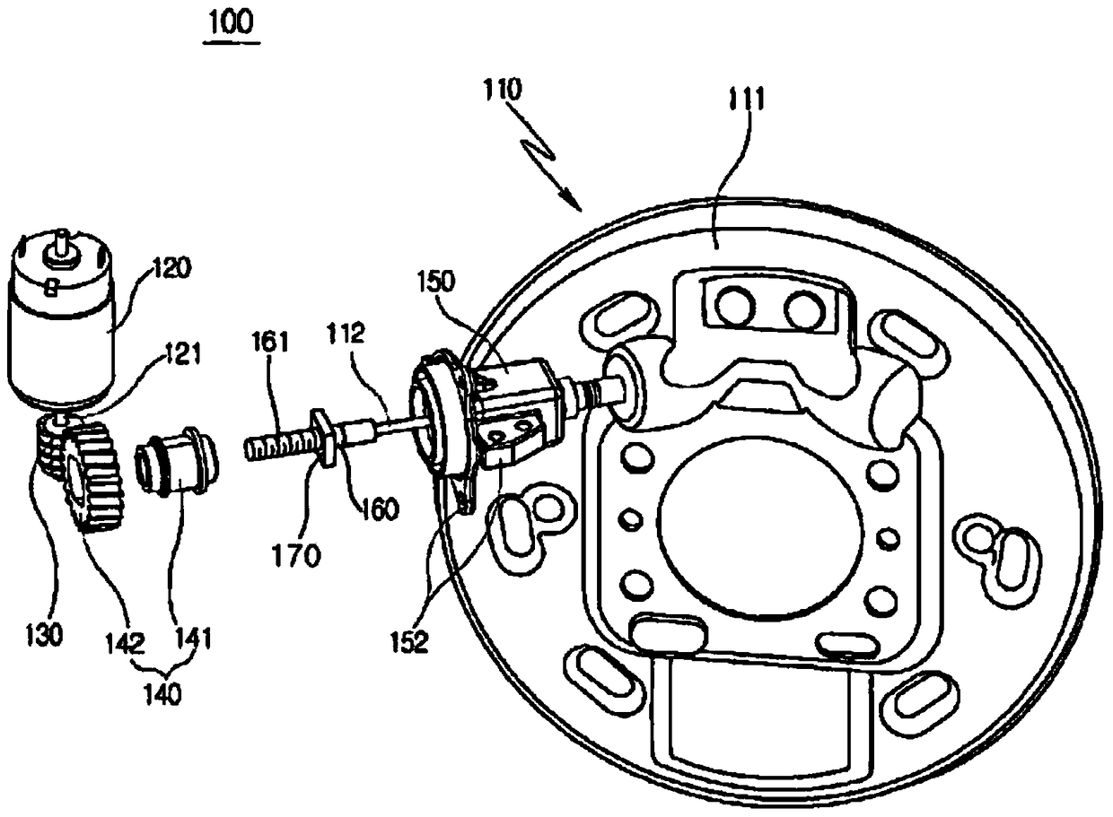
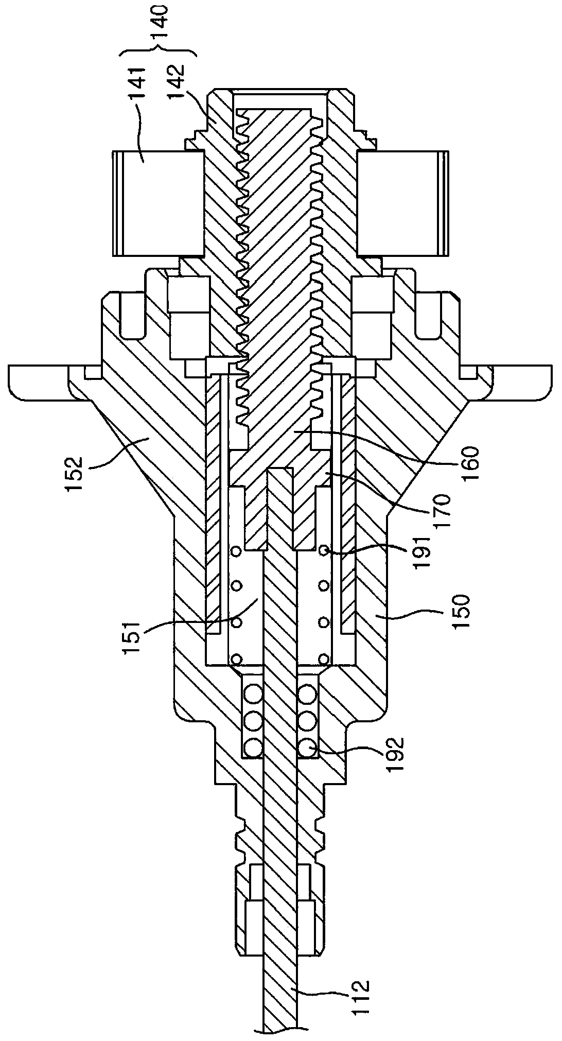
[0056] figure 1 To show an exploded perspective view of an electronic parking brake for a vehicle according to an embodiment of the present invention, figure 2 In order to show a cross-sectional view of the combination structure of the screw rod and the housing in the electronic parking brake for vehicles according to an embodiment of the present inven...


PUM


Abstract

An electronic parking brake for a vehicle includes: a drum assembly braking a wheel; a driving motor generating a driving force for braking the wheel; a driving gear coupled to a driving shaft of the driving motor and rotated; a driven gear coupled to the driving gear and rotated; a cable operating member geared to the driven gear, and advanced or retreated by the rotation of the driven gear so as to operate a parking cable of the drum assembly; an elastic member restricting the movement of the cable operating member; a current sensing unit configured to sense a driving current of the driving motor and provide the sensed driving current; and a control unit configured to operate the driving motor during brake release, and control the operation of the driving motor based on a change of the driving current inputted from the current sensing unit during brake release.

Description

technical field [0001] The present invention relates to an electronic parking brake for a vehicle and a control method thereof, in particular to a motor on DIH (MOD) type electronic parking brake that moves a cable working member arranged to tighten the parking cable. The elastic member in the space part restrains the movement of the working member of the cable to change the driving current of the drive motor when the brake is released, so that the position of the working member of the cable can be known according to the change of the driving current and the vehicle that can prevent the actuator casing from being damaged Electronic parking brake and its control method. Background technique [0002] Generally, the parking brake of an automobile is a device that brakes the rear or front wheels of the vehicle in order to maintain a parked state when the vehicle is parked. [0003] Now the rear wheels of vehicles are increasingly using disc brakes instead of drum brakes. Since ...

Claims


Application Information

Patent Timeline
Patent Type & Authority Patents(China)
IPC IPC(8): B60T7/08B60T17/22
CPCB60T11/046B60T13/02B60T13/746F16D51/10F16D65/22F16D2121/24F16D2125/40F16D2125/60
Inventor 郑夏珉
Owner HYUNDAI MOBIS CO LTD
Why Eureka
Try Eureka