
Pneumatic tire

A technology for pneumatic tires and tires, applied in tire parts, tire tread/tread pattern, transportation and packaging, etc., can solve the problems of reduced handling stability on dry roads, reduced tire-to-land ratio, and large opening width, etc. The effect of maintaining wet performance, improving performance on snow, and suppressing partial wear

Active Publication Date: 2016-01-27
SUMITOMO RUBBER IND LTD
View PDF7 Cites 18 Cited by
  • Summary
  • Abstract
  • Description
  • Claims
  • Application Information

AI Technical Summary

Problems solved by technology

[0005] However, since the main groove of Patent Document 1 has a convex portion in the groove, there is a tendency for drainage to decrease.
In addition, since the main groove of Patent Document 1 has a large opening width on the tread surface, the land ratio of the tire is lowered, and the steering stability on dry road surfaces tends to be lowered.

Method used


Image

  • Pneumatic tire
  • Pneumatic tire
  • Pneumatic tire

Examples


Embodiment

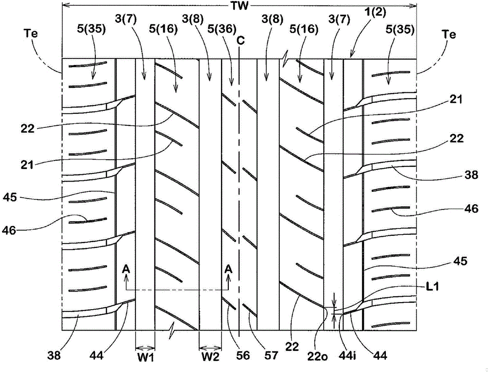
[0085] According to the specifications in Table 1, a trial production with figure 1 The size of the basic pattern is 215 / 55R16 pneumatic tires. As a comparative example, a tire in which the inclination angles of the inner groove wall and the outer groove wall of the shoulder main groove are the same and no shallow bottom portion is not provided in the middle sipe was trial-manufactured. The handling stability on dry road, wet road performance and snow performance of each test tire were tested. The general specifications and test methods of each test tire are as follows.

[0086] Mounting rim: 16×6.5J

[0087] Tire internal pressure: front wheel 210kPa, rear wheel 200kPa

[0088]

[0089] The steering stability when the following test vehicle was driven on a test course on a dry road surface was evaluated by the driver's senses. The results are represented by a score of 100 for Comparative Example 1, and the larger the numerical value, the better the steering stability. ...


PUM


Abstract

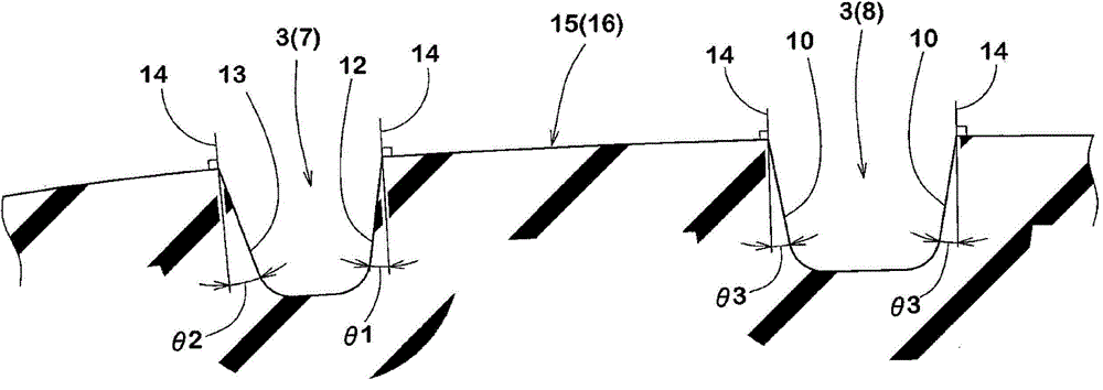
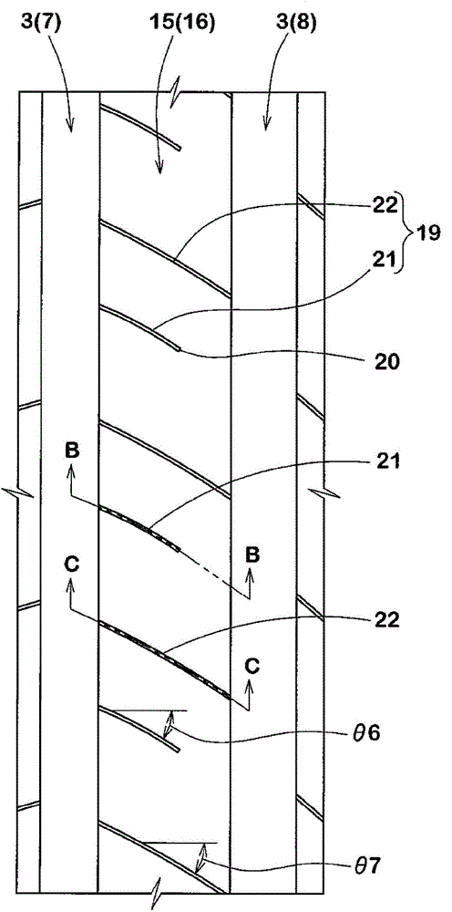
The present invention provides a pneumatic tire capable of maintaining the properties of a trunk road and a wet road while improving the performance of the pneumatic tire on the snow. The tread (2) of the pneumatic tire (1) comprises a main channel (3) and a land part (5). The main channel (3) is composed of an inner trench wall (12) on the side of a tire equatorial (C), and an outer trench wall (13) on the side of a tread end (Te). The tilt angle of the outer trench wall (13) is larger than that of the inner trench wall (12). The land part (5) is composed of an inner land part (15) adjacent to the tire equatorial (C) of the main channel (3). The inner land part (15) is provided with a siping (19) in communication with the main channel (3). The siping (19) is composed of a bottom surface (24) and a shallow bottom part (25) that is raised at the end portion of the main channel (3).

Description

technical field [0001] The present invention relates to a pneumatic tire capable of maintaining dry performance and wet performance and improving snow performance. Background technique [0002] For example, Patent Document 1 below proposes a pneumatic tire in which the shape of the groove wall of the main groove is improved in order to improve on-snow performance. Specifically, the main groove of the pneumatic tire of Patent Document 1 includes an upper wall surface extending from an edge of the groove and a lower wall surface having an inclination angle smaller than that of the upper wall surface with respect to the radial direction of the tire in a cross section perpendicular to the groove. department. In addition, convex portions having a triangular cross-section are provided at intervals in the tire circumferential direction on the lower wall portion. [0003] For such a main groove, when driving on snow, the above-mentioned convex portion strongly compacts the snow in...

Claims


Application Information

Patent Timeline
Patent Type & Authority Applications(China)
IPC IPC(8): B60C11/13B60C11/03B60C11/12
Inventor 菊池洋
Owner SUMITOMO RUBBER IND LTD
Learn More