


Quick Research
Generate reliable direction feasibility study reports for your R&D in just a few steps.

Technical Q&A
Discover and master advanced knowledge NOW. Basics, ideas, possibilities, all at once.

Find Solutions
As an expert in R&D theories, this can generate solutions to your technical problems instantly.

Evaluate Feasibility
Analyze your overall solution with one click, know your potential R&D risks in advance.

Monitor Landscape
Get weekly tech updates, stay abreast of the latest tech innovations and key insights.
Rapid microstructure forming and manufacturing method
A manufacturing method and microstructure technology, applied in the direction of manufacturing tools, turning equipment, turning equipment, etc., can solve the problems of low material removal rate, high cost of processing equipment, low processing efficiency, etc., and achieve the effect of low cost
- Summary
- Abstract
- Description
- Claims
- Application Information
AI Technical Summary
Problems solved by technology
Method used
Image

Examples
Embodiment 1
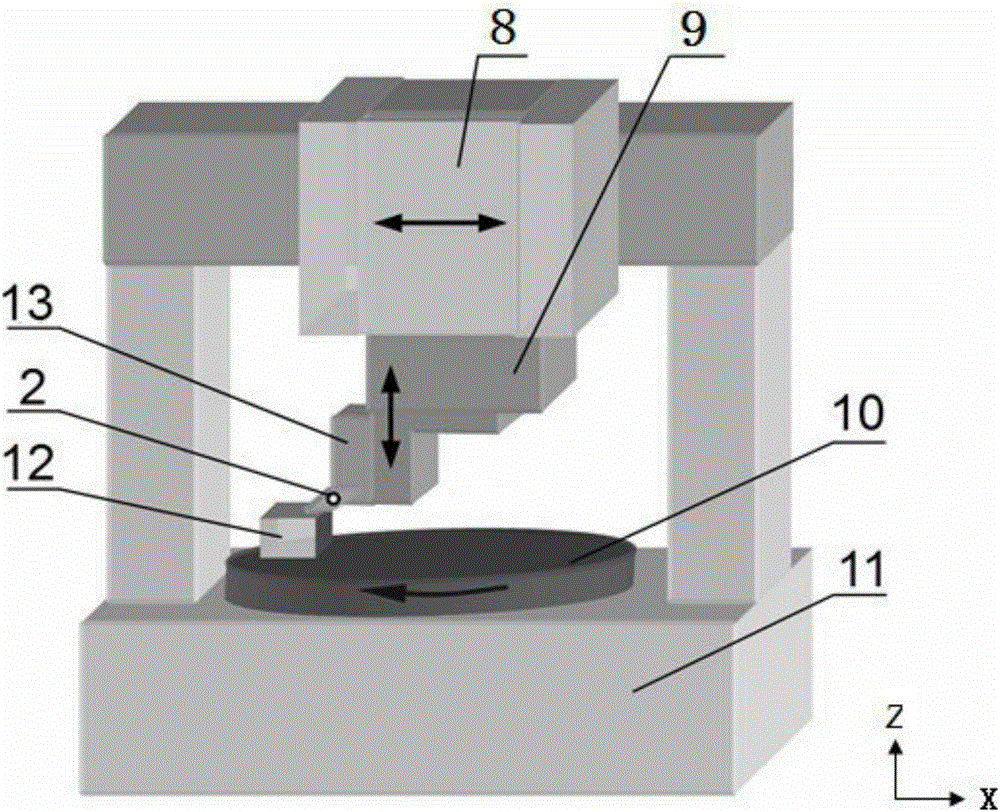
[0022] Embodiment 1: First, install the processed aluminum alloy workpiece 12 above the horizontal rotary table 10, adjust the center distance between the processed aluminum alloy workpiece 12 and the horizontal rotary table 10, and ensure that the target microstructure is formed at an appropriate cutting speed. Precision turning process. Subsequently, the second slider 9 is single-controlled to make the tool clamping device 13 feed in the vertical cutting depth direction, and gradually reduce the height position of the installed tool 2, so that the aluminum alloy workpiece 12 is covered by hard alloy in each revolution cycle. Tool 2 is turned at a constant depth of cut to reach the design height of the target microstructure. Finally, the target microstructure rapidly formed on the aluminum alloy workpiece 12 is detected, and the optical microscope detection results along the horizontal direction 12-1 and the cross-sectional direction 12-2 of the microstructure are as follows ...
Embodiment 2
[0023] Embodiment 2: First, the aluminum alloy workpiece 12 to be processed is installed above a fixed horizontal workbench, and the distance between the aluminum alloy workpiece 12 to be processed and the cemented carbide tool 2 with a microstructure cutting edge is adjusted. Subsequently, the first slider 8 and the second slider 9 are simultaneously controlled to make the tool clamping device 13 feed in the vertical cutting depth direction and the horizontal cutting direction, and gradually reduce the height position of the installed tool 2, so that the aluminum alloy workpiece 12 It is planed by the cemented carbide tool 2 at a constant depth of cut, and finally reaches the design value of the height of the target microstructure.
[0024] After the processing is completed, the processing tool 2 for the rapid prototyping of the microstructure can be reused after being cleaned by ultrasonic vibration.
PUM
 Abstract
Description
Claims
Application Information
 - R&D Engineer
- R&D Manager
- IP Professional
- Industry Leading Data Capabilities
- Powerful AI technology
- Patent DNA Extraction
Browse by: Latest US Patents, China's latest patents, Technical Efficacy Thesaurus, Application Domain, Technology Topic, Popular Technical Reports.
© 2024 PatSnap. All rights reserved.Legal|Privacy policy|Modern Slavery Act Transparency Statement|Sitemap|About US| Contact US: help@patsnap.com