


Quick Research
Generate reliable direction feasibility study reports for your R&D in just a few steps.

Technical Q&A
Discover and master advanced knowledge NOW. Basics, ideas, possibilities, all at once.

Find Solutions
As an expert in R&D theories, this can generate solutions to your technical problems instantly.

Evaluate Feasibility
Analyze your overall solution with one click, know your potential R&D risks in advance.

Monitor Landscape
Get weekly tech updates, stay abreast of the latest tech innovations and key insights.
Three-dimensional binocular camera platform experimental device
A binocular camera and experimental device technology, applied in the direction of machines/supports, supporting machines, mechanical equipment, etc., can solve the problems of inability to control in real time, high cost, low precision, etc., and achieve strong practicability, simple control, high precision effect
- Summary
- Abstract
- Description
- Claims
- Application Information
AI Technical Summary
Problems solved by technology
Method used
Image


Examples
Embodiment 1
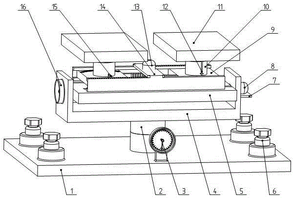
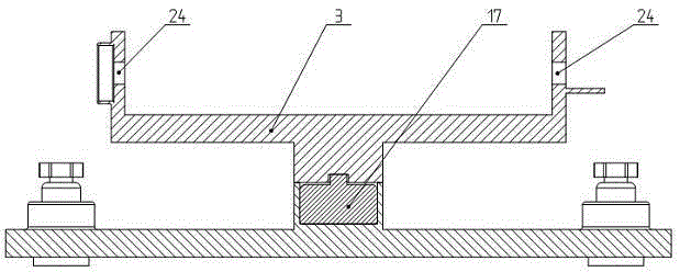
[0032] see Figure 1~Figure 9 , the three-dimensional binocular camera pan-tilt experimental device, the center of the base 1 is provided with a servo motor 17, the servo motor 17 is connected and drives the turntable 2 to rotate, so as to realize the left and right rotation of the two cameras as a whole, and dynamically capture the moving object; the turntable 2 is connected to the support frame 4, and the support frame is connected to the camera support plate 5 driven by the servo motor 2 for pitching and swinging. When the control command is sent to the servo motor 2 8, the servo motor 2 8 drives the camera support plate 5 to realize two The overall up-and-down pitching action of the camera increases the angle range of the dynamic shooting of the camera; the left and right sides of the camera support plate 5 are respectively installed with two camera supports that are driven by the servo motor 3 13 through the spur rack and pinion mechanism 18 to adjust the distance 9. By c...
Embodiment 2
[0034] This embodiment is basically the same as Embodiment 1, and the features are as follows: a level measuring instrument 3 is provided at the front of the base 1 to detect whether the device is in a horizontal position; each of the four corners of the base 1 is provided with a The horizontal height fine-tuning device 6 is used to adjust the device so that it is in a horizontal position. In the 3D binocular camera shooting experiment, the angle selection of the camera has a great influence on the acquired image feature information. When the camera shoots the same object at different angles, the feature information obtained is quite different. Because some experimental environments are relatively harsh, for example, there is no flat shooting platform, and the tabletop of the experimental table is old and uneven, which will cause the shooting angle of the camera to change, which is likely to cause visual errors of the camera, and the obtained images have a relatively large impa...
Embodiment 3
[0036] Such as Figure 1~Figure 8 As shown, this three-dimensional binocular camera pan-tilt experimental device is an example of real-time adjustment of camera angle and distance. For details, see figure 1 and figure 2 , the level measuring instrument 3 located at the front of the base 1 can detect whether the whole experimental device is in a horizontal position, if not, the level height fine-tuning device 6 located at the four corners of the base 1 can be adjusted for level adjustment. The base turntable 3 located in the central position of the base 1 is as image 3 In the position shown, it is connected to the support frame 4, the controller sends a control command to the servo motor one 17, the servo motor one 17 rotates, and drives the base turntable 3 to rotate left or right, and the left and right cameras on the support frame 4 realize The action of turning left or right as a whole.
[0037] The support frame 4 is connected to the camera support bearing plate 5, the...
PUM
 Abstract
Description
Claims
Application Information
 - R&D Engineer
- R&D Manager
- IP Professional
- Industry Leading Data Capabilities
- Powerful AI technology
- Patent DNA Extraction
Browse by: Latest US Patents, China's latest patents, Technical Efficacy Thesaurus, Application Domain, Technology Topic, Popular Technical Reports.
© 2024 PatSnap. All rights reserved.Legal|Privacy policy|Modern Slavery Act Transparency Statement|Sitemap|About US| Contact US: help@patsnap.com