A negative pressure fan with self-cleaning function

A negative pressure fan, functional technology, applied in home appliances, space heating and ventilation details, household heating, etc., can solve the problems of fan damage, increase the workload of employees, etc., to improve firmness, safety, and solve Difficult to clean up

Active Publication Date: 2018-09-04
苏州腾辉环保科技有限公司
View PDF6 Cites 0 Cited by
  • Summary
  • Abstract
  • Description
  • Claims
  • Application Information

AI Technical Summary

Problems solved by technology

[0003] However, due to the fact that the negative pressure fan will inevitably fall into a lot of dust during the working process, most companies now find a fixed time to clean it in their spare time, and must be cleaned when necessary. Only when the fan is disassembled can it be thoroughly cleaned, which greatly increases the workload of the employees. At the same time, during the disassembly process of the cycle, it is easy to cause certain damage to the fan itself. Therefore, the production of the existing negative pressure fan Technology still needs to be further improved

Method used


Image

  • A negative pressure fan with self-cleaning function
  • A negative pressure fan with self-cleaning function

Examples


Embodiment

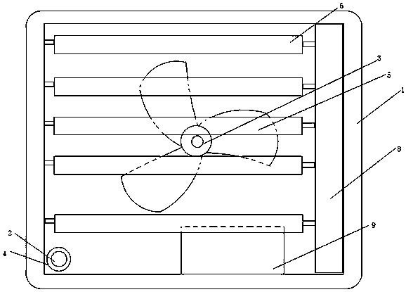
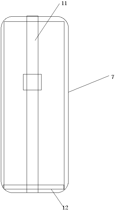
[0030] Such as figure 1 and figure 2 The shown negative pressure fan with self-cleaning function includes: housing 1, motor 2, rotating shaft 3, pulley 4, fan blade 5, deflector 6, casing 7, electrostatic precipitator 8 and control device 9 , The electrostatic precipitator 8 is composed of an anode plate, a cathode plate, a rectifier, a dirt bag and a controller.

[0031] The relationship between the above components is as follows:

[0032] The motor 2 is arranged below the casing 1, the rotating shaft 3 is arranged on a support plate in the middle of the casing 1, a turntable is arranged on the support plate, and the pulley 4 is arranged on the motor 2. The fan blade 5 is arranged on the rotating shaft 3, the deflector 6 is movably connected to both sides of the casing 1, the casing 7 is fixed on the casing 1, and the electrostatic precipitator 8 is located in the housing 1, the motor 2 and the electrostatic precipitator 8 are connected to the control device 9, the pulley...

Embodiment 2

[0042] The structure of the negative pressure fan with self-cleaning function in the working method of the negative pressure fan with self-cleaning function described in this embodiment is the same as that in Embodiment 1.

[0043] In this embodiment, a working method of a negative pressure blower with self-cleaning function, the specific working method is as follows:

[0044] (1): First connect the negative pressure fan to the power supply, and then the negative pressure fan will enter the working state;

[0045](2): After the power is turned on, the motor 2 starts to rotate, and the pulley 4 is set on the motor 2, so the pulley 4 rotates with the motor 2;

[0046] (3): During the rotation of the pulley 4, since the pulley 4 and the turntable are connected by a belt, the turntable will also rotate continuously under the drive of the pulley 4;

[0047] (4): During the rotation of the turntable, it will drive the rotating shaft 3 to rotate together. Since the fan blade 5 is in...


PUM


Abstract

The invention discloses a negative-pressure draught fan with the self-cleaning function. The negative-pressure draught fan comprises a shell, a motor, a rotary shaft, a belt wheel, fan blades, air deflectors, a housing, an electrostatic dust collection device and a control device. The electrostatic dust collection device is arranged in the shell. The motor and the electrostatic dust collection device are both connected with the control device. The electrostatic dust collection device is composed of an anode plate, a cathode plate, a rectifier, a dirt collecting bag and a controller. According to the negative-pressure draught fan with the self-cleaning function, the electrostatic dust collection device is arranged in the negative-pressure draught fan, dust is sucked to a dust centralized region through the anode plate and the cathode plate, dust is collected through the dirt collecting bag, the dirt collecting bag is replaced after the dust is collected to a certain degree, the dust is poured out, the dirt collecting bag is cleaned, and the whole working process of the draught fan can be automatically and intelligently controlled through the control device. The problem that a draught fan is difficult to clean is well solved, and then the requirements of clients are better met.

Description

technical field [0001] The invention relates to a fan, in particular to a negative pressure fan with self-cleaning function. Background technique [0002] The negative pressure fan uses the cooling principle of air convection and negative pressure ventilation. It is a kind of natural inhalation of fresh air from the opposite side of the installation site --- the door or window, and the indoor sultry gas is quickly forced out of the room. Any poor ventilation problems will be eliminated. The machine can be improved, and the cooling and ventilation effect can reach 90%-97%. [0003] However, due to the fact that the negative pressure fan will inevitably fall into a lot of dust during the working process, most companies now find a fixed time to clean it in their spare time, and must be cleaned when necessary. Only when the fan is disassembled can it be thoroughly cleaned, which greatly increases the workload of the employees. At the same time, during the disassembly process of...

Claims


Application Information

Patent Timeline
Patent Type & Authority Patents(China)
IPC IPC(8): F24F13/28
Inventor 徐浩
Owner 苏州腾辉环保科技有限公司
Why Eureka
Try Eureka