
Inkpad holder for self-inking stamp and device and method for producing the same

A technology for holders and printing pads, which is applied to the equipment for injection molding such printing pad holders, and the field of manufacturing such printing pad holders. It can solve the problems of polluting the insertion chamber, contamination of the seal, and dirt from the user, and achieves a fixed and reinforced effect. Effect

Active Publication Date: 2016-01-13
刻乐圃印章制造斯高贝有限两合公司
View PDF8 Cites 0 Cited by
  • Summary
  • Abstract
  • Description
  • Claims
  • Application Information

AI Technical Summary

Problems solved by technology

On the downside, filaments may form at the corners during the blanking process when manufacturing the stamp pad
When inserting the stamp, ink-soaked filaments may contaminate the insertion chamber
In addition, this technique has the disadvantage that due to the bulges of the pad filling, especially on the long sides, manual handling of the pad holder becomes difficult or contamination can occur on the stamp or on the user's part
Thus, it is not possible to eliminate the problem that the stamp pad may contaminate the stamp due to ridges and filament formation on the corner areas

Method used


Image

  • Inkpad holder for self-inking stamp and device and method for producing the same
  • Inkpad holder for self-inking stamp and device and method for producing the same
  • Inkpad holder for self-inking stamp and device and method for producing the same

Examples


Embodiment Construction

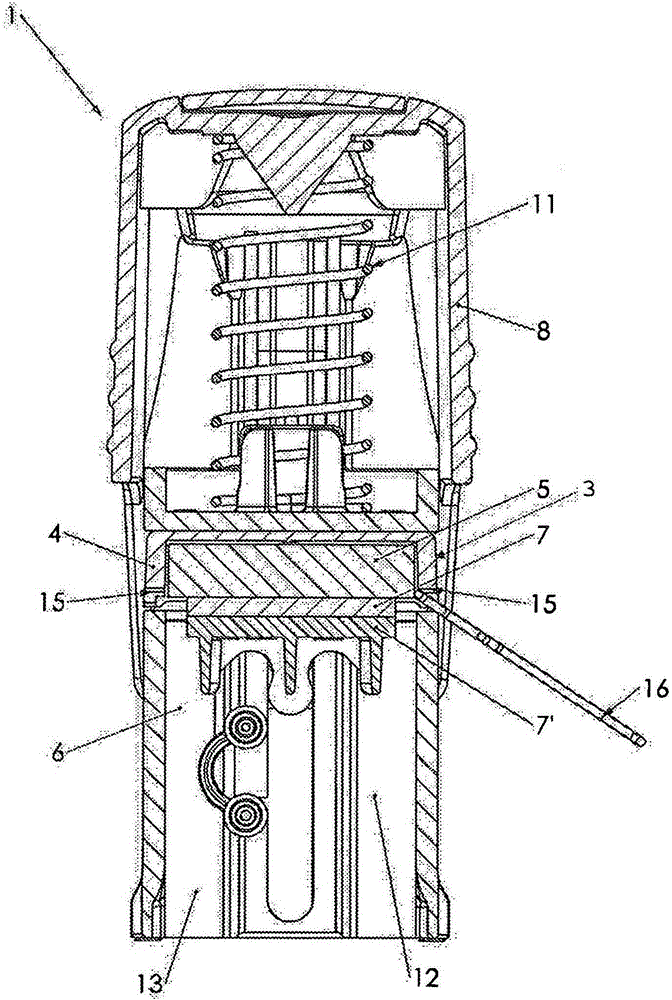
[0043] exist figure 1 1 shows a conventional ink-returning stamp 1, which has a frame-like stamp housing 2 (hereinafter referred to as housing 2). The housing 2 has an insertion chamber 3 for a stamping pad holder 4 arranged exchangeably therein, in which a stamping pad 5 is accommodated. To replace the pad holder 4, according to figure 1 A paper clip 16 is used, with which it engages in the recess 15 of the stamp holder 4 . Alternatively, the insertion chamber can be open towards both sides, so that the pad holder 4 without the recess 15 can be pressed out of the insertion chamber 3 . A stamping unit 6 is also provided inside the housing 2, and the stamping unit includes a printing plate 7 with stamped characters mounted on a printing plate support 7'. Stamping unit 6 in figure 1 is shown in the inking position against the printing pad 5 .

[0044] For actuating the ink return stamp 1 , an actuating bow 8 is provided, which in the exemplary embodiment shown is fitted ont...


PUM

PropertyMeasurementUnit
widthaaaaaaaaaa

Abstract

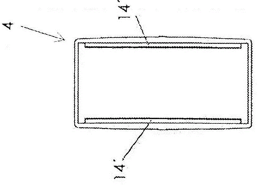
The invention relates to an inkpad holder (4) for arrangement in an insertion compartment (3) of a self-inking stamp (1), said inkpad holder (4) having a bottom (15) and walls (16, 17) projecting therefrom which delimit a receiving space for receiving an inkpad (5). At least one wall (16) of the inkpad holder (4) has a retaining web (14) protruding into the receiving space in order to retain the inkpad (5), the retaining web (14) extending over the entire length of the wall (16, 17). The invention further relates to a device (18) and a method for producing such an inkpad holder (4).

Description

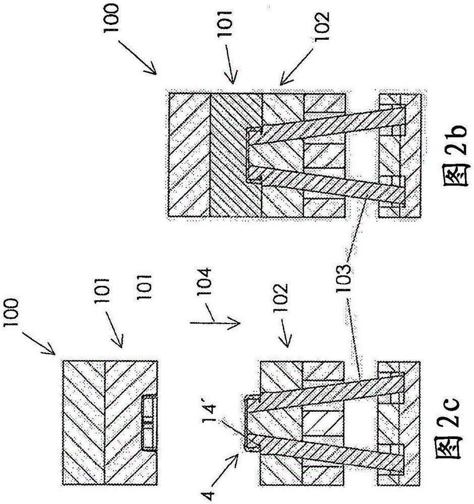
technical field [0001] The invention relates to a pad holder for placement in an insertion chamber of an ink-returning stamp, the pad holder having a bottom and a wall protruding from the bottom, said bottom and said wall defining a housing for accommodating an ink pad space, wherein at least one wall of the ink pad holder has a retaining edge protruding into the accommodating space for holding the ink pad. [0002] Furthermore, the invention relates to a device for injection molding such a pad holder, which device comprises an injection mold with a first mold part and a second mold part, which in the closed position encloses a mold cavity, wherein the first A mold part and a second mold part are mounted movably relative to each other in an opening or closing direction. [0003] Finally, the invention relates to a method for producing such an ink pad holder in an injection molding process. Background technique [0004] For example, EP 1603755 B1 discloses a re-inking stamp...

Claims


Application Information

Patent Timeline
Patent Type & Authority Applications(China)
IPC IPC(8): B41K1/40B41K1/54B29C45/44B29C45/03
CPCB29C45/04B29C45/40B29C45/4421B41K1/36B41K1/40B41K1/54B29C45/401B29C45/66B29K2101/00B29L2031/7678
Inventor E·法贝尔
Owner 刻乐圃印章制造斯高贝有限两合公司
Learn More