
A power collection terminal with a usb OTG interface and its debugging and upgrading method

A power acquisition and interface technology, applied in control/regulation systems, instruments, computer control, etc., can solve problems such as affecting the work efficiency of on-site operators, inability to debug, and few hardware interfaces, saving operation time and improving work efficiency. , the effect of reducing production costs

Active Publication Date: 2017-11-28
NINGBO SANXING MEDICAL & ELECTRIC CO LTD
View PDF6 Cites 0 Cited by
  • Summary
  • Abstract
  • Description
  • Claims
  • Application Information

AI Technical Summary

Problems solved by technology

[0002] Existing power collection terminals have few external hardware interfaces, commonly used interfaces include RS232 interface and RS485 interface, debugging operation and meter reading operation cannot be carried out at the same time, this type of power collection terminal will increase the workload of on-site operators; secondly , the current debugging and upgrading method is to realize the information interaction between PC and other external equipment and power collection terminal through the above-mentioned RS232 interface and RS485 interface
At present, there are multiple RS485 interfaces on the power collection terminal, which are used for debugging, meter reading and other operations. The power collection terminal is equipped with multiple chips and circuits related to the RS485 interface, which increases the production cost of the power collection terminal. Too many RS485 interfaces affect the design of the appearance and structure of the power collection terminal. Based on the above situation, it is necessary to develop a power collection terminal with fewer RS485 interfaces, or only one RS485 interface, but if only one RS485 interface is set , the existing problem is that the power collection terminal can only complete meter reading or debugging, but the meter reading function of the power collection terminal is necessary, so setting up a power collection terminal with an RS485 interface can only complete the meter reading operation, although by reducing the RS485 interface The quantity is conducive to reducing the production cost of the power collection terminal, and will not affect the design of the appearance structure of the power collection terminal. However, only one RS485 interface is set, and there are still many shortcomings that have not been overcome, including if the power collection terminal is debugged In the process, the RS485 interface cannot be used as a normal meter reading, that is, the meter reading cannot be realized, and the amount of data required for the debugging process is relatively large, but the RS485 interface has a low memory reading rate, which cannot meet the interaction of large data volumes and affects real-time performance; When the collection terminal performs meter reading operation, the RS485 interface cannot be used as a debugging interface, that is, it cannot debug the process
[0003] Secondly, in the current debugging and upgrading method of power collection terminal, the debugging process needs to open the cover of the power collection terminal (the overall structure of the power collection terminal is small, and there are not too many external interfaces, and the upgrade debugging interface is generally installed in the power collection terminal. internal), the process is relatively cumbersome, resulting in a heavy workload for on-site operators and affecting the work efficiency of on-site operators

Method used


Image

  • A power collection terminal with a usb OTG interface and its debugging and upgrading method

Examples


Embodiment Construction

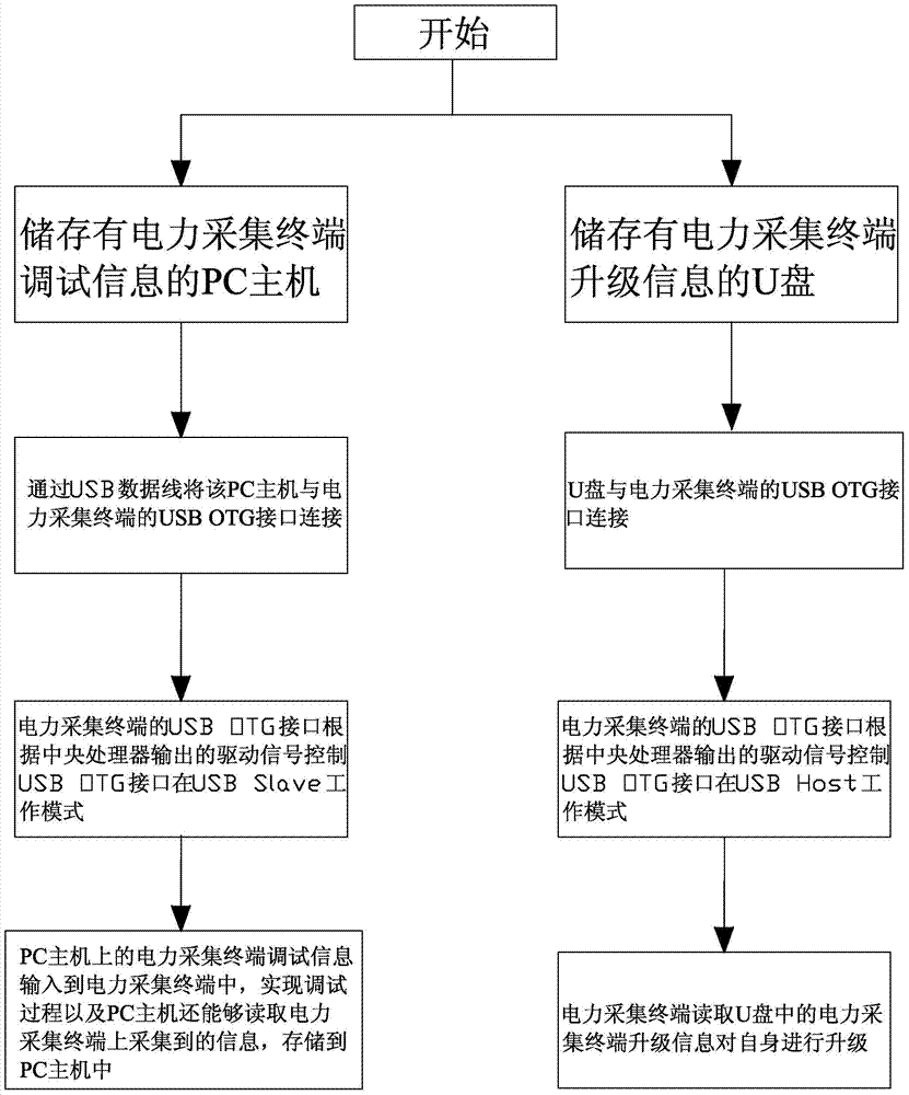
[0016] Attached below figure 1 The present invention is described in further detail.

[0017] The present invention is a power collection terminal with a USB OTG interface, which includes a power collection terminal body, the power collection terminal body is provided with an RS485 interface; the power collection terminal is provided with a central processing unit, a USB OTG interface, a power module and a For the identification module of the ID line state of the identification USB OTG interface, the USB OTG interface, the identification module, and the central processing unit are connected sequentially, and the central processing unit is also electrically connected with the power supply module and the USB OTG interface; the identification module identification Output the ID line status of the USB OTG interface and feed back the result to the central processing unit; the central processing unit judges the interface type of the peripheral device according to the sampling result...


PUM


Abstract

The invention discloses a power collection terminal with a USB OTG interface and a debugging upgrade method thereof. The power collection terminal comprises a power collection terminal body, and is provided with a central processor, the USB OTG interface, a power supply module and an identification module which is used for identifying the state of an ID line of the USB OTG interface. The identification module identifies the state of the ID line of the USB OTG interface and feeds a result back to the central processor. The central processor determines the type of an external interface according to a sampling result. A corresponding enable signal is output according to the type of the external interface to control the work state of the power supply module, and a corresponding drive signal is output to convert the work mode of the USB OTG interface. The USB OTG interface is controlled to convert between a USB Slave work mode and a USB Host work mode according to a drive signal output by the central processor. The power collection terminal provided by the invention realizes meter reading and debugging processes, has the advantage of high transfer rate, and can meet the exchange of a large amount of data.

Description

technical field [0001] The invention relates to a power collection terminal with a USB OTG interface and a debugging and upgrading method thereof. Background technique [0002] Existing power collection terminals have few external hardware interfaces, commonly used interfaces include RS232 interface and RS485 interface, debugging operation and meter reading operation cannot be carried out at the same time, this type of power collection terminal will increase the workload of on-site operators; secondly , the current means of debugging and upgrading is also through the above-mentioned RS232 interface and RS485 interface to realize the information interaction between the PC and other external equipment and the power collection terminal. At present, there are multiple RS485 interfaces on the power collection terminal, which are used for debugging, meter reading and other operations. The power collection terminal is equipped with multiple chips and circuits related to the RS485 i...

Claims


Application Information

Patent Timeline
Patent Type & Authority Patents(China)
IPC IPC(8): G05B19/042
CPCG05B19/0428G05B2219/2612
Inventor 郑坚江刘宁陈杰
Owner NINGBO SANXING MEDICAL & ELECTRIC CO LTD
Learn More