
Reservoir flow velocity measurement method based on pressure sensor

A pressure sensor and flow velocity measurement technology, applied in the application field, can solve the problems of limited applicable occasions, inflexible use, interference with fluid form, etc., to achieve the effect of improving measurement accuracy, saving labor costs, and high measurement accuracy

Inactive Publication Date: 2016-01-13
XIAN UNIV OF POSTS & TELECOMM +1
View PDF13 Cites 3 Cited by
  • Summary
  • Abstract
  • Description
  • Claims
  • Application Information

AI Technical Summary

Problems solved by technology

The propeller flowmeter will disturb the fluid shape during measurement, and is not suitable for the measurement of turbulent flow and boundary layer. When the fluid velocity is small, the measurement error is large and there is a measurement dead zone; the measurement error of the Pitot tube is large, and its inlet must go deep into the measurement point, which interferes with the fluid form; the particle image velocimeter needs to use strong light to obtain tracer particle motion information during measurement, which limits its application; the laser Doppler velocimeter has a complex structure, is not flexible to use, and is very expensive. SMEs can't afford it
[0003] Pressure sensors have been put into use in many fields, but their use method is single, usually only used to measure pressure data and liquid level height data
In addition, the pressure sensor itself drifts seriously, so it is hardly used for flow rate measurement

Method used


Image

  • Reservoir flow velocity measurement method based on pressure sensor
  • Reservoir flow velocity measurement method based on pressure sensor
  • Reservoir flow velocity measurement method based on pressure sensor

Examples


Embodiment Construction

[0014] In order to describe in detail the system structure, module connections, working conditions and purpose of the data processing algorithm of the present invention, a detailed description will be given below in conjunction with specific examples and accompanying drawings.

[0015] Example one

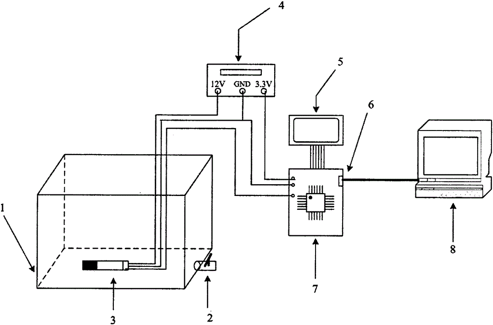
[0016] refer to figure 1 , the system structure of the present invention is described in detail below:

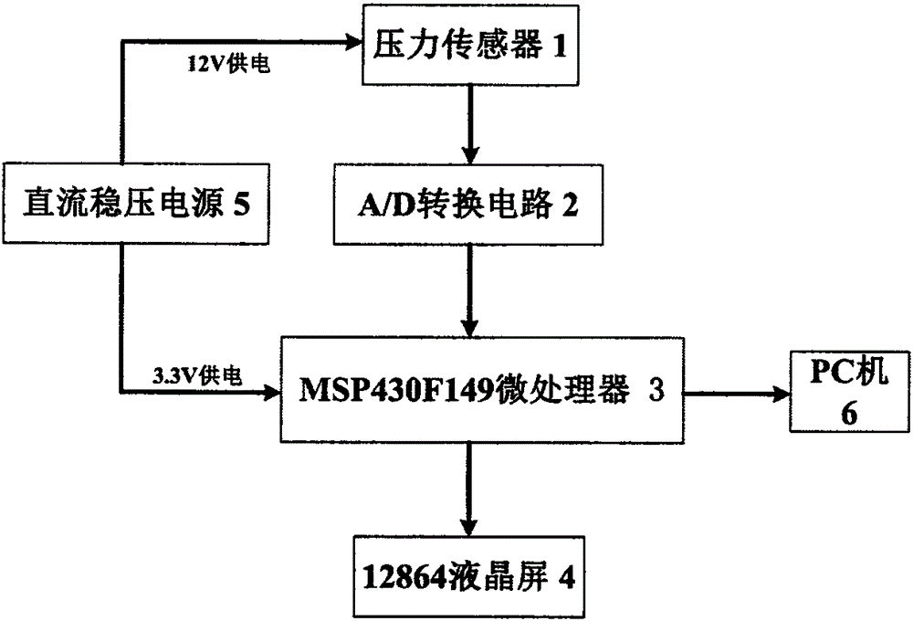
[0017] A method for measuring the flow rate of a water storage tank based on a pressure sensor. Its system structure includes a water tank 1, a faucet 2, a pressure sensor 3, a DC stabilized power supply 4, a 12864 LCD screen 5, a serial port 6, an MSP430F149 microprocessor 7, and a PC Machine 8.

[0018] The water tap 2 is fixed on the bottom of the water tank 1 and is responsible for controlling the opening and closing of the water flow. The pressure sensor 3 is placed at the bottom of the water tank. Since it is placed in the water, it is necessary to take corresponding wa...


PUM


Abstract

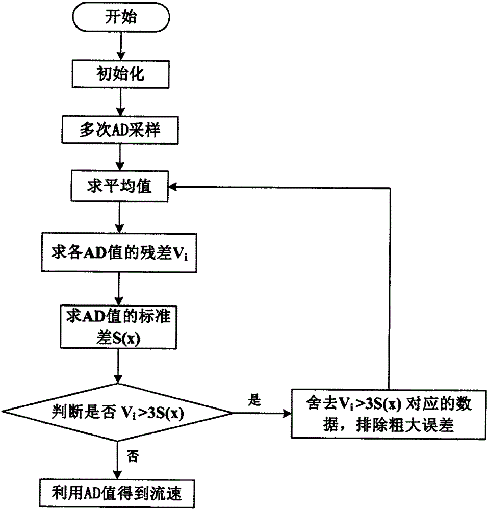
The invention discloses a reservoir flow velocity measurement method based on a pressure sensor, which belongs to the field of automatic control and flow velocity measurement. A water tank, a tap, a pressure sensor, a DC voltage-stabilizing power supply, a serial port, an MSP430F149 microprocessor, a data processing algorithm, a 12864 liquid crystal display, a PC and the like are included, wherein the water tank is used for storing water; the tap is used for controlling on and off of a water flow; the pressure sensor is placed at the bottom part of the water tank for sensing changes of liquid level pressure inside the water tank and transmitting the acquired pressure data to the MSP430F149 microprocessor; through the corresponding data processing algorithm, gross errors are removed, accurate AD data are obtained, liquid level height information and flow velocity information are finally converted and displayed on the 12864 liquid crystal display; the DC voltage-stabilizing power supply provides power for each module; and by using the serial port, the height information and the flow velocity information are displayed on an upper computer of the PC. Thus, the purposes of measuring the liquid level height and the flow velocity of the reservoir at the same time by using the pressure sensor are realized.

Description

technical field [0001] The invention relates to the application fields of flow velocity measurement technology, automatic control and the like, in particular to a method for measuring the flow velocity of a water storage tank based on a pressure sensor. Background technique [0002] Flow velocity is one of the basic parameters to determine the characteristics of water flow, which is closely related to our life, and is especially widely used in industrial production and agricultural irrigation. For example, the pipeline transmission of oil, the transportation of raw materials in the production workshop, the monitoring of the water level and flow of the reservoir, the management of the water output of the reservoir in agricultural irrigation, the early warning of the flow rate of the water body in the port channel, etc. It can be seen that the accurate measurement of the flow rate is very necessary. Nowadays, propeller current meter, Pitot tube, particle image velocimeter, an...

Claims


Application Information

Patent Timeline
Patent Type & Authority Applications(China)
IPC IPC(8): G01P5/00
Inventor 赵小强张朋波何亚风高强许曰强彭红梅邓丹
Owner XIAN UNIV OF POSTS & TELECOMM
Learn More