
Compound-eye-simulating sensing and imaging information collecting system with high imaging definition

An information collection, compound eye imitation technology, applied in image enhancement, image data processing, control without feedback, etc., to achieve the effect of avoiding sharpness, improving sharpness, and low cost of compound eye function

Inactive Publication Date: 2016-01-13
蒋春花
View PDF1 Cites 0 Cited by
  • Summary
  • Abstract
  • Description
  • Claims
  • Application Information

AI Technical Summary

Problems solved by technology

[0004] The technical problem to be solved by the present invention is to provide an imitation compound eye sensing imaging information acquisition system, which solves the problem of adaptively adjusting the image sampling field of view according to the average brightness of the target scene (i.e., the ambient light intensity) range of technical issues

Method used


Image

  • Compound-eye-simulating sensing and imaging information collecting system with high imaging definition
  • Compound-eye-simulating sensing and imaging information collecting system with high imaging definition
  • Compound-eye-simulating sensing and imaging information collecting system with high imaging definition

Examples


Embodiment 1

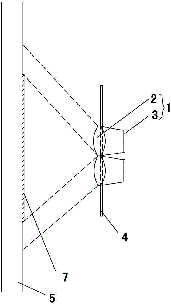
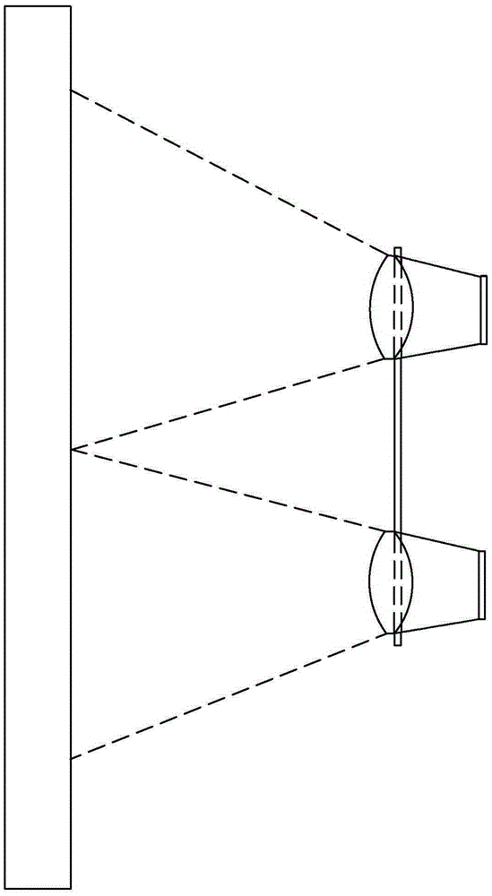
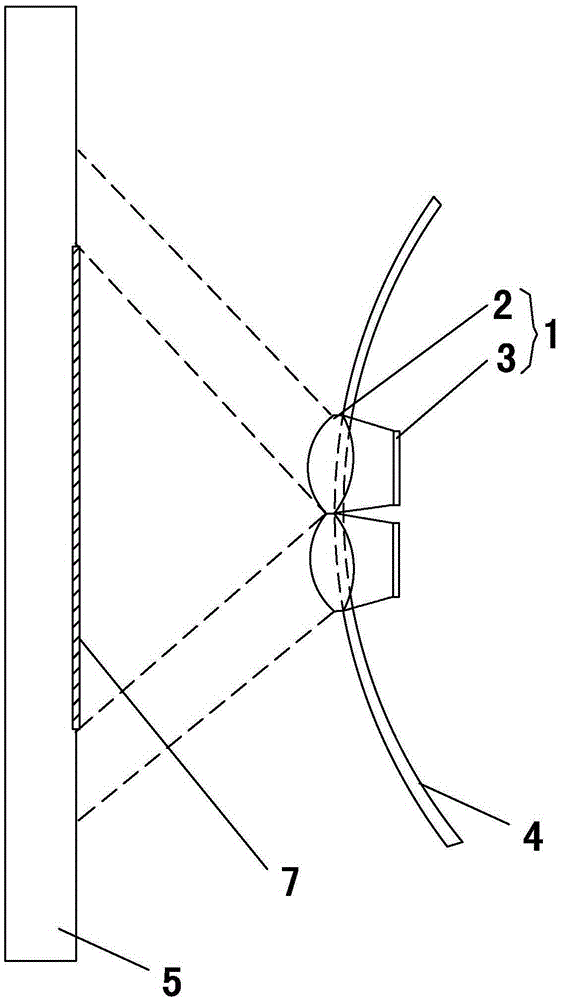
[0024] See Figure 1-5 , Figure 8 with Figure 10 , an imitation compound eye perception imaging information acquisition system, comprising: a compound eye lens array for collecting target scene information by compound eyes, the compound eye lens array includes four ommatidium image acquisition units 1, and is formed by splicing four guide rails 4 in an X-shaped symmetrical manner The four ommatidium image acquisition units 1 are located on the four guide rails 4 respectively, and are distributed symmetrically according to the center point 6 of the guide rail assembly, wherein the ommatidium image acquisition unit 1 includes a lens 2 and is located on the four guide rails. The imaging device 3 at the rear end of the lens 2;

[0025] A processor module connected to each imaging device, the processor module is suitable for extracting the average brightness of the target scene obtained by each imaging device, and controls each ommatidium image acquisition unit 1 along the desc...

Embodiment 2

[0039] See Figure 1-5 , Figure 8 with Figure 10 , a working method of an imitation compound eye perception imaging information acquisition system based on embodiment 1, the imitation compound eye perception imaging information acquisition system includes: a compound eye lens array for compound eyes to collect target scene information, the compound eye lens array includes four The ommatidium image acquisition unit 1 is a guide rail assembly formed by splicing four guide rails 4 in an X-shaped symmetrical manner. The four ommatidium image acquisition units 1 are respectively located on the four guide rails 4, and are symmetrical according to the center point 6 of the guide rail assembly distribution, wherein the ommatidium image acquisition unit 1 includes a lens 2, and an imaging device 3 positioned at the rear end of the lens 2;

[0040] A processor module for connecting with each imaging device, the processor module is suitable for extracting the brightness average value...


PUM


Abstract

The invention relates to a compound-eye-simulating sensing and imaging information collecting system with high imaging definition. The system comprises a compound eye lens array for collecting target scene information through compound eyes. The compound eye lens array comprises four small eye image collecting units and a guide rail assembly symmetrically spliced by four guide rails according to the X shape. The four small eye image collecting units are located on the four guide rails respectively and symmetrically distributed according to the center of the guide rail assembly. Each small eye image collecting unit comprises a lens, an imaging device located at the rear end of the lens, and a processor module connected with the imaging device. Each processor module is suitable for extracting the luminance value of a target scene obtained by the corresponding imaging device and controls the corresponding small eye image collecting unit according to the luminance value to move synchronously along the corresponding guide rail in the same direction or opposite directions at a constant speed so that the vision range of the compound eye lens array can be adjusted.

Description

technical field [0001] The invention relates to an imitation compound eye perception imaging information collection system. Background technique [0002] In the prior art, the digital micromirror device is used to sample the scene image. Since the change of light intensity directly affects the image quality, when the light is strong, the definition is high, and when the light is weak, the definition decreases and the noise increases; although There are many software processing methods to improve the clarity in low light, but the processing effect is not good, for example, the nearest neighbor interpolation method, bilinear interpolation method, bicube interpolation method, etc. The bilinear interpolation method has higher reconstruction accuracy than the nearest neighbor interpolation method, and the image restoration effect is better, but the image will appear jagged and blurred. Although the reconstruction effect of the bicubic interpolation method is better than the form...

Claims


Application Information

Patent Timeline
Patent Type & Authority Applications(China)
IPC IPC(8): G01C11/02G06T5/50
CPCG01C11/02G05D3/10G06T5/50
Inventor 不公告发明人
Owner 蒋春花
Learn More