
Foldable gantry crane capable of ascending and descending

A lifting device and gantry technology, which is applied in the direction of trolley cranes, hoisting equipment braking devices, cranes, etc., can solve the problems of inability to adjust the height, occupy a large space, and inconvenient transportation, so as to strengthen the structural stability and improve the carrying capacity , the effect of reducing the space occupied

Inactive Publication Date: 2016-01-13
CHANGZHOU INST OF TECH
View PDF9 Cites 34 Cited by
  • Summary
  • Abstract
  • Description
  • Claims
  • Application Information

AI Technical Summary

Problems solved by technology

[0004] (1) The height of the gantry frame is fixed, and the height cannot be adjusted according to the specific space of the construction site, which brings some inconvenience to the use;
[0005] (2) Since the height of the gantry frame is not adjustable and is an integral structure, it takes up a lot of space during transportation, and it also brings inconvenience to the transportation of the gantry lifting device
However, in this application, it is still difficult to solve the problem that the gantry takes up a large space only by adjusting the height of the gantry, and it is still very inconvenient to transport when the beam is long; in addition, the application uses lifting pulleys and The lifting function of the gantry is realized by means of fixed pulleys. Although it is convenient to use, the winding of the wire rope is complicated and cumbersome. The wire rope turntable can only be used for the lifting of the gantry and cannot be used for other purposes.

Method used


Image

  • Foldable gantry crane capable of ascending and descending
  • Foldable gantry crane capable of ascending and descending
  • Foldable gantry crane capable of ascending and descending

Examples


Embodiment

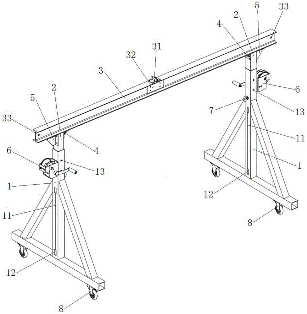
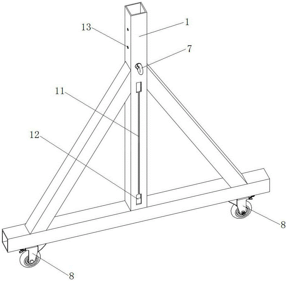
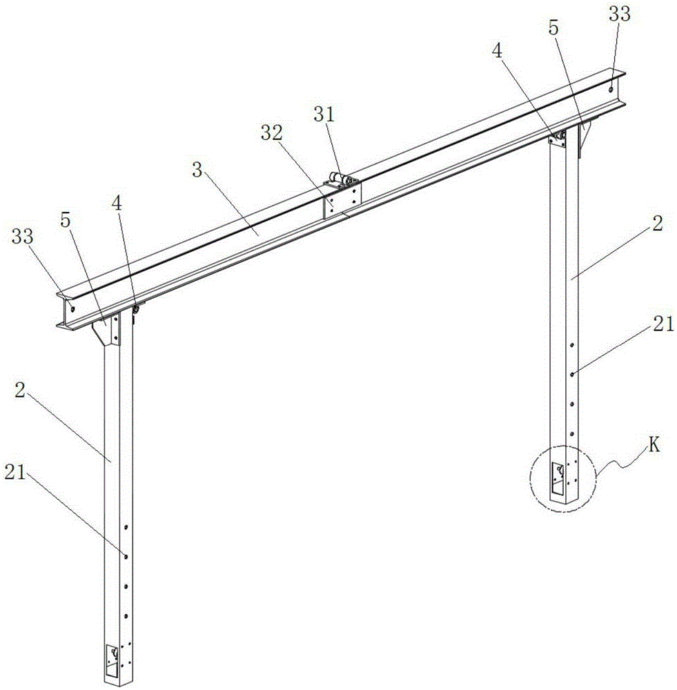
[0035] combine figure 1 , figure 2 and image 3 As shown, a liftable and foldable gantry lifting device in this embodiment has lifting and folding functions, and it includes a crossbeam 3 and legs arranged on both sides of the crossbeam 3. Lifting support rod 2, fixed leg 1 telescopically matched with the lifting support rod 2, a lifting mechanism is provided between the lifting support rod 2 and the fixed leg 1, and diagonal braces are arranged on both sides of the fixed leg 1, which are welded into a triangular shape Stable structure; the above-mentioned lifting mechanism includes a manual winch 6 with self-locking function, lifting lug 7 and pulley 23, and the manual winch 6 and lifting lug 7 are installed on both sides of the upper part of the fixed leg 1 respectively, wherein the manual winch 6 passes through the winch seat Installed on the outside of the fixed leg 1, the lifting lug 7 is welded on the inner side of the fixed leg 1, and the lower part of the fixed leg ...


PUM


Abstract

The invention discloses a foldable gantry crane capable of ascending and descending, and belongs to the field of carrying tools. The foldable gantry crane capable of ascending and descending comprises a beam and supporting legs arranged on the two sides of the beam. Each supporting leg comprises a lifting supporting rod connected with the beam and a fixed supporting leg in telescopic fit with the lifting supporting rod, wherein a lifting mechanism is arranged between the lifting supporting rod and the fixed supporting leg. The beam is cut off from the middle, the two parts formed after cutting are hinged together, and the hinging portions are fixedly connected through a connecting plate. The two ends of the beam are connected with the upper portions of the lifting supporting rods through hinges respectively. After the connecting plate is detached, the beam can be bent downwards, and then the supporting legs on the two sides of the beam can be retracted inwards. Height adjustment can be performed as needed when the gantry crane is in use, so that use is easy and convenient. The beam can be lowered and folded when the gantry crane is not in use, so that occupied space is reduced, and transport is facilitated. The gantry crane is simple in structure, convenient to operate and low in cost.

Description

technical field [0001] The invention relates to a lifting device, in particular to a liftable and foldable gantry lifting device. Background technique [0002] The small and medium-sized gantry lifting device is a small lifting support platform developed according to the needs of handling equipment, warehouse import and export, lifting and maintenance of heavy equipment and material transportation in the daily production of small and medium-sized factories. It is widely used in mold manufacturing factories , auto repair factories, mines, civil construction sites and other occasions that require lifting. The use of gantry lifting devices can realize lifting mechanization, reduce manpower, reduce production and operation costs, and improve work efficiency. [0003] The currently used gantry lifting device mainly has the following disadvantages: [0004] (1) The height of the gantry frame is fixed, and the height cannot be adjusted according to the specific space of the const...

Claims


Application Information

Patent Timeline
IPC IPC(8): B66C19/02B66C5/02
Inventor 田文彤杨辉卜金纬陆晨胡志林沈冬郭庆
Owner CHANGZHOU INST OF TECH
Learn More