Supporting ring for hot-press gluing machine

A technology of support ring and bonding machine, applied in container manufacturing machinery, rigid/semi-rigid container manufacturing, paper/cardboard containers, etc., can solve problems such as easy deformation of cylinders

Inactive Publication Date: 2016-01-13
CHONGQING XINSHUI MACHINERY MFG
View PDF0 Cites 0 Cited by
  • Summary
  • Abstract
  • Description
  • Claims
  • Application Information

AI Technical Summary

Problems solved by technology

[0005] The present invention intends to provide a support ring for a thermocompression bonding machine to solve the problem that the cylinder is easily deformed by its own weight

Method used


Image

  • Supporting ring for hot-press gluing machine
  • Supporting ring for hot-press gluing machine

Examples


Embodiment Construction

[0016] The present invention will be described in further detail below by means of specific embodiments:

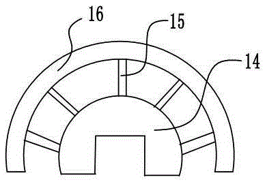
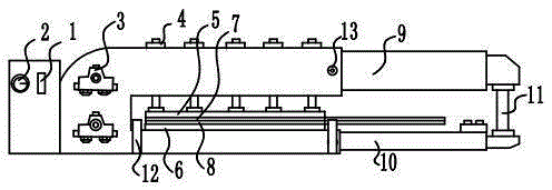
[0017] The reference signs in the drawings of the specification include: start switch 1, temperature adjustment button 2, diverter and flow valve 3, hydraulic cylinder 4, upper pressing plate 5, lower pressing plate 6, upper insulating plate 7, lower insulating plate 8, upper sliding plate 9 , Lower plate 10, positioning plate 11, support ring 12, pull bolt 13, block 14, screw 15, arc block 16.

[0018] Such as figure 1 As shown, the support ring used for the thermocompression bonding machine includes a block 14 , a screw 15 and an arc block 16 snapped on the machine body. Block 14 is left and right symmetrical structure, and the peripheral shape of block 14 is a semicircle, and the inner peripheral shape of block 14 is rectangular; The part is arc-shaped, so the inside of the block 14 is a rectangle and the outside is a semi-circular structure, which can make the suppo...


PUM


Abstract

The invention relates to an auxiliary structure of cylinder gluing equipment and particularly discloses a supporting ring for a hot-press gluing machine. The supporting ring comprises a clamping block clamped on a machine body, multiple adjusting screws connected to the clamping block in a threaded manner and radially distributed, and an arc-shaped block connected with the heads of the screws. The situation that a machined cylinder is deformed due to the influence of dead weight can be avoided.

Description

technical field [0001] The invention relates to an auxiliary structure of cylinder bonding equipment, in particular to a support ring for a heat-press bonding machine. Background technique [0002] Thermocompression bonding is the final process in the formation of cardboard tubes. In the past, after gluing, an iron block was used to press the overlapping joints of the cardboard tubes, which could neither ensure uniform pressure nor sufficient pressure. The glue is not in full contact with the cardboard, which affects the firmness of the bond. In order to better complete the thermocompression bonding process, a support ring for thermocompression bonding machines has been developed. [0003] Existing thermocompression bonding machines generally include a fuselage, an upper platen, a lower platen and a hydraulic cylinder. The upper platen is provided with a heating wire for heating, and the thick cardboard tube coated with adhesive after rolling is fixed for later use. The i...

Claims


Application Information

Patent Timeline
Patent Type & Authority Applications(China)
IPC IPC(8): B31B1/64B31B1/62B31B50/64B31B50/62
Inventor 廖佳袁
Owner CHONGQING XINSHUI MACHINERY MFG
Why Eureka
Try Eureka