A Multidirectional Positioning Fixture for Turbo Pump Welding

A technology for positioning fixtures and turbo pumps, applied in welding equipment, auxiliary welding equipment, welding/cutting auxiliary equipment, etc., can solve problems affecting welding quality, etc., and achieve the effects of improving efficiency, realizing flexible adjustment, and realizing integrated clamping

Inactive Publication Date: 2016-11-30
HARBIN INST OF TECH
View PDF5 Cites 0 Cited by
  • Summary
  • Abstract
  • Description
  • Claims
  • Application Information

AI Technical Summary

Problems solved by technology

[0003] In order to solve the problem that the welding quality is seriously affected by the existence of gaps between the various components of the main part of the existing turbopump structure during the welding process, the present invention further proposes a multi-directional positioning fixture for turbopump welding

Method used


Image

  • A Multidirectional Positioning Fixture for Turbo Pump Welding
  • A Multidirectional Positioning Fixture for Turbo Pump Welding
  • A Multidirectional Positioning Fixture for Turbo Pump Welding

Examples


specific Embodiment approach 1

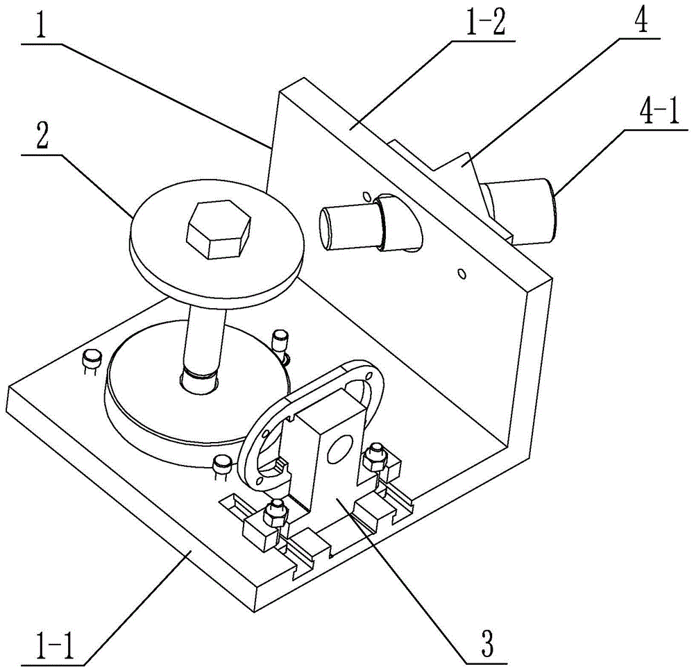
[0020] Specific implementation mode one: combine figure 1 , figure 2 , image 3 , Figure 4 , Figure 5 and Figure 6 Describe this embodiment. This embodiment includes an L-shaped operating panel 1, a vertical positioning assembly 2, a lateral positioning assembly 3 and a nozzle positioning assembly 4. The L-shaped operating panel 1 includes a horizontal plate 1-1 and a vertical plate 1-1. 2. The horizontal board 1-1 and the vertical board 1-2 are arranged vertically and are fixedly connected as a whole, and the vertical positioning assembly 2 and the horizontal positioning assembly 3 are both arranged on the horizontal board 1-1 and horizontally The positioning assembly 3 is located in front of the vertical positioning assembly 2, and the nozzle positioning assembly 4 is arranged on the vertical plate 1-2;

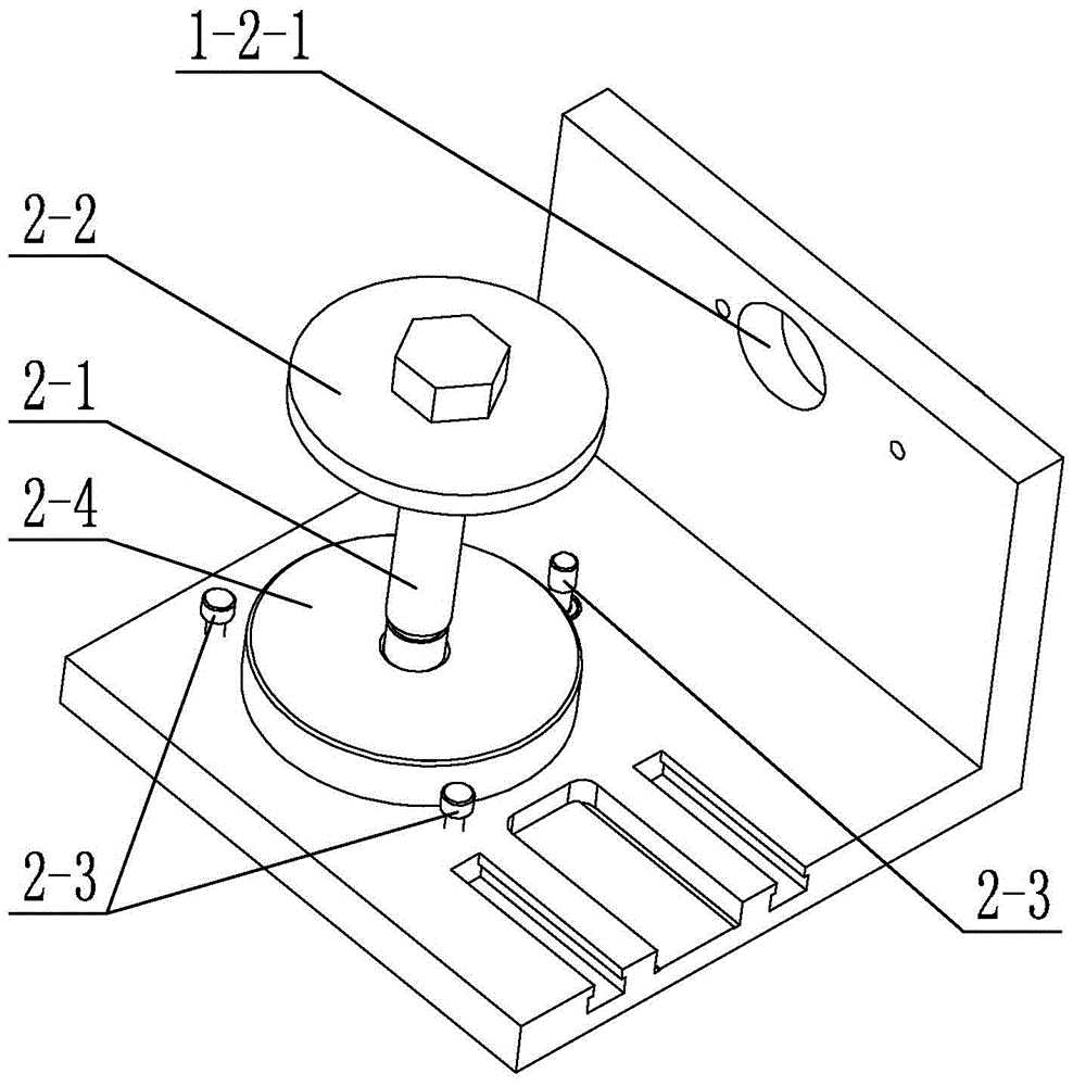
[0021] The vertical positioning assembly 2 includes a mandrel 2-1, a pressing block 2-2, a base 2-4 and at least two first fixing bolts 2-3, and the base 2-4 is fi...

specific Embodiment approach 2

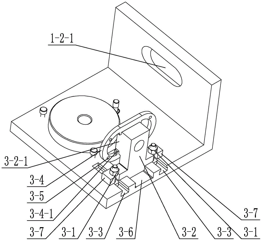
[0025] Specific implementation mode two: combination figure 1 , image 3 , Figure 4 and Figure 6 To illustrate this embodiment, the lateral positioning assembly 3 in this embodiment also includes two positioning bolts 3-1, two sub-sliding rails 3-3 and two pulling ears 3-7, and the horizontal plate 1-1 is Two sub-sliding rails 3-3 are provided, and the two sub-sliding rails 3-3 are respectively located on both sides of the main sliding rail 3-6, and each sub-sliding rail 3-3 is parallel to the main sliding rail 3-6. A positioning bolt 3-1 is arranged in the strip slide rail 3-3, and a pulling ear 3-7 is fixedly connected to both sides of the horizontal positioning block 3-2, and the pulling ear 3-7 is connected with the positioning bolt 3-1. One-to-one correspondence is provided, and each pull ear 3-7 slides and fits with the sub-slide rail 3-3 where the positioning bolt 3-1 is located through its corresponding positioning bolt 3-1.

[0026] In this embodiment, the setti...

specific Embodiment approach 3

[0027] Specific implementation mode three: combination figure 1 , Figure 4 and Figure 6 This embodiment is described. In this embodiment, both the pressing block 2-2 and the base 2-4 are disc-shaped and arranged coaxially. In this embodiment, the disc-shaped pressing block 2-2 corresponds to the shape of the pump casing 5-1, and such setting is more conducive to its close contact with the pump casing 5-1. The disc-shaped base 2-4 corresponds to the shape of the pump base 5-3, and such setting is more conducive to its close contact with the pump base 5-3. Other unmentioned structures and connections are the same as those in the first or second embodiment.


PUM


Abstract

The invention relates to a multidirectional positioning clamp and discloses a multidirectional positioning clamp for welding of a turbopump. The problem that gaps between all parts of a body part of an existing turbopump structure exist in the welding process to seriously affect the welding quality is solved. The multidirectional positioning clamp for welding of the turbopump comprises an L-shaped operation board, a vertical positioning assembly, a transverse positioning assembly and a nozzle positioning assembly, wherein the L-shaped operation board comprises a horizontal board and a vertical board which are perpendicularly arranged and are fixedly connected into a whole; the vertical positioning assembly and the transverse positioning assembly are arranged on the horizontal board; the transverse positioning assembly is located in front of the vertical positioning assembly; the nozzle positioning assembly is arranged on the vertical board; a mandrel is sleeved with a pump shell, a diversion outer shell and a pump base of the turbopump in sequence from top to bottom; a compression pressure block is tightly attached to the pump shell of the turbopump; a compression pressure sheet is fixedly connected to the end face, close to the mandrel, of a transverse positioning block and tightly attached to an air inlet flange of the turbopump. The multidirectional positioning clamp for welding of the turbopump is used for the welding process of the turbopump.

Description

technical field [0001] The invention relates to a multidirectional positioning fixture, which belongs to the field of mechanical processing. Background technique [0002] The structure of the turbo pump that needs to be welded mainly includes the pump casing, the guide casing, the pump base, the intake flange and the nozzle ring. According to the characteristics of the turbo pump structure, it is required to realize the integrated welding of the structure, the tight fit of the connected parts and the flushness of the connected end faces. During the welding process, there are gaps between the various components of the main part of the turbo pump structure, which seriously affects the welding quality. At present, there is no welding fixture for this type of pump structure with components such as flanges and nozzles. Contents of the invention [0003] In order to solve the problem that the welding quality is seriously affected by the existence of gaps between the various com...

Claims


Application Information

Patent Timeline
Patent Type & Authority Patents(China)
IPC IPC(8): B23K37/04
CPCB23K37/0443
Inventor 蔡创陶汪王亚军张亮李俐群
Owner HARBIN INST OF TECH
Why Eureka
Try Eureka