Eureka AIR delivers breakthrough ideas for toughest innovation challenges, trusted by R&D personnel around the world.
Material circulation conveying device
What is Al technical title?
Al technical title is built by PatSnap Al team. It summarizes the technical point description of the patent document.
A conveying device and material circulation technology, applied in conveyors, mechanical conveyors, transportation and packaging, etc., can solve the problems of wasting manpower and affecting processing efficiency, and achieve the effects of convenient operation, improved processing efficiency, and convenient adjustment.
Active Publication Date: 2017-07-25
PEARL RIVER PIANO GROUP
View PDF6 Cites 0 Cited by
Summary
Abstract
Description
Claims
Application Information
AI Technical Summary
This helps you quickly interpret patents by identifying the three key elements:
Problems solved by technology
Method used
Benefits of technology
Problems solved by technology
Therefore, it affects the processing efficiency and wastes manpower
Method used
Image
Click on the blue label to locate the original text in one second.
Reading with bidirectional positioning of images and text.
Examples
Embodiment Construction
[0046] The present invention will be described in further detail below.
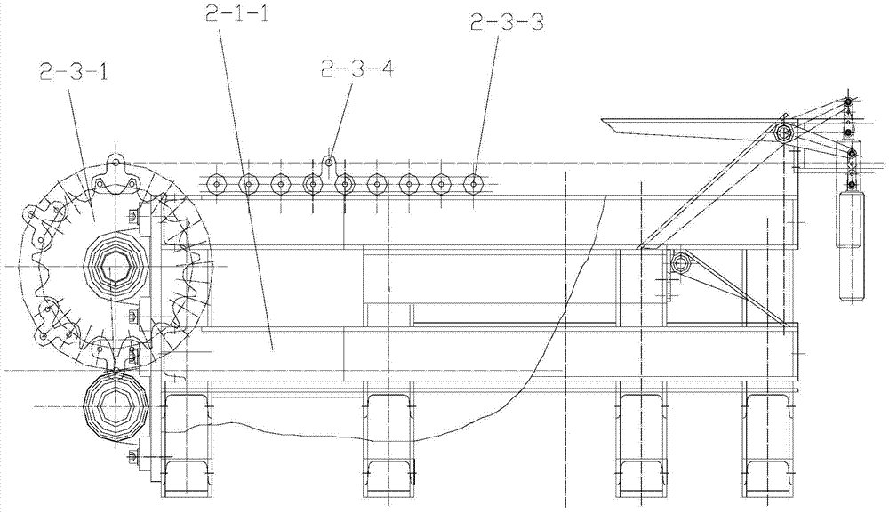
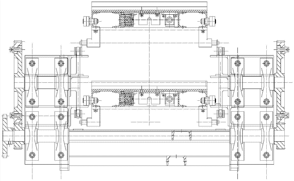
[0047] The material circulation conveying device includes: conveying frame, conveying vehicle, chain transmission mechanism, motor, upper guide rail, lower guide rail, front middle guide rail, rear middle guide rail, rear sinking guide rail, front upper inclined bridge, front lower inclined bridge, rear downward inclined Bridge, back down ramp, back up ramp, back up valve.
[0048] The conveying frame includes a head frame, a tail frame and a plurality of intermediate frames. The head frame, the middle frame connected in series, and the tail frame are connected in series from front to back. When the present invention is used in a polishing machine, the polishing machine has a plurality of polishing units, so a plurality of intermediate frames are selected to build a certain conveying length compatible with the polishing units.
[0049] The number of conveying vehicles is multiple, driven by the same ch...
PUM
Abstract
The invention relates to a circulating conveying device for materials, and belongs to the technical field of conveying devices. The circulating conveying device comprises a conveying frame, a conveying trolley which comprises front wheel and a rear wheel and is used for carrying materials, a chain transmission mechanism pulling the front end of the conveying trolley, a motor for driving the conveying trolley to horizontally move anticlockwise in a plane through the chain transmission mechanism, an upper guide rail, a lower guide rail, a front middle guide rail, a rear middle guide rail, a rear sinking guide rail, a front upper skew bridge, a front lower skew bridge, a rear lower skew bridge, a rear lower skew slope, a rear upper skew bridge and a rear upper valve, wherein the upper guide rail, the lower guide rail, the front middle guide rail, the rear middle guide rail and the rear sinking guide rail are horizontally installed on the conveying frame and used for supporting the rear wheel of the conveying trolley, and the front upper skew bridge, the front lower skew bridge, the rear lower skew bridge, the rear lower skew slope, the rear upper skew bridge and the rear upper valve are installed on the conveying frame. The circulating conveying device has the beneficial effects that the structure is ingenious, operation is convenient, the conveying trolley can horizontally move to conduct transportation in the vertical plane in a circulating manner, and the materials can be conveyed in a circulating manner.
Description
technical field [0001] The present invention relates to a conveying device, in particular to a circular conveying device for circularly conveying materials in a vertical plane. Background technique [0002] During the piano production process, the panels on the surface of the piano need to be polished. In order to improve the processing efficiency, the polishing machine adopts the form of multi-axis polishing, that is, a plurality of polishing units are arranged in sequence along the conveying direction of the plate, each polishing unit is equipped with a main shaft, and a main shaft drives a polishing wheel to rotate. Once the plate is transported on the production line, it can be polished by multiple polishing wheels in turn, which effectively improves the processing efficiency. [0003] The existing plate conveying device is a linear translational type, that is, the plate is conveyed in a straight line on the horizontal plane, and passes through a plurality of polishing ...
Claims
Application Information
Patent Timeline
Application Date:The date an application was filed.
Publication Date:The date a patent or application was officially published.
First Publication Date:The earliest publication date of a patent with the same application number.
Issue Date:Publication date of the patent grant document.
PCT Entry Date:The Entry date of PCT National Phase.
Estimated Expiry Date:The statutory expiry date of a patent right according to the Patent Law, and it is the longest term of protection that the patent right can achieve without the termination of the patent right due to other reasons(Term extension factor has been taken into account ).
Invalid Date:Actual expiry date is based on effective date or publication date of legal transaction data of invalid patent.