
Clamping device for steel plate of case for computer

A clamping device and computer technology, applied in positioning devices, clamping, metal processing mechanical parts, etc., can solve the problems of cumbersome operation, reduced steel plate work efficiency, complex overall structure, etc. The effect of work efficiency

Inactive Publication Date: 2016-01-06
CHONGQING ZHIRUIDE TECH
View PDF0 Cites 13 Cited by
  • Summary
  • Abstract
  • Description
  • Claims
  • Application Information

AI Technical Summary

Problems solved by technology

Steel plate is one of the four major varieties of steel. In developed countries, the output of steel plate accounts for more than 50% of the total production just now. With the development of my country's national economy, the demand for steel plate is also increasing. According to different needs, steel plate needs to be produced For further processing, the fixtures used for processing steel plates are extremely important. The existing fixtures usually have a complex overall structure and cumbersome operation, which reduces the work efficiency of steel plate processing

Method used


Image

  • Clamping device for steel plate of case for computer

Examples


Embodiment Construction

[0013] The present invention will be described in further detail below by means of specific embodiments:

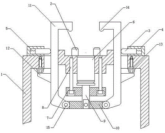
[0014] The reference signs in the drawings of the description include: frame 1, boss 2, top column 3, guide hole 4, spring 5, cylinder 6, support plate 7, guide post 8, push rod 9, linkage plate 10, jaws 11. Limiting block 12, screw 13, protrusion 14, pin shaft 15.

[0015] The embodiment is basically as attached figure 1 Shown: the clamping device of computer chassis steel plate, including frame 1 and linkage mechanism, linkage mechanism includes cylinder 6, support plate 7, push rod 9 and linkage plate 10, cylinder 6 is arranged on frame 1, push rod 9 The lower end of the lower end is fixedly connected with the middle part of the linkage plate 10; the frame 1 is provided with a clamping mechanism symmetrically left and right along the center line of the frame 1, and the clamping mechanism includes a boss 2 for placing a steel plate and a top that is slidingly connected...


PUM


Abstract

The invention discloses a clamping device for a steel plate of a case for a computer. The clamping device comprises a rack and a linkage mechanism, wherein the linkage mechanism comprises a cylinder, a support plate and a linkage frame, and the cylinder is arranged on the rack; and clamping mechanisms are arranged on the rack in the form of vertical symmetry along the centre line of the rack, each clamping mechanism comprises a boss used for placing the steel plate, an ejection column slidably connected with the rack, a spring arranged between the ejection column and a base, a guide hole, a guide column arranged in the support plate, a clamping jaw used for clamping the steel plate, and a limit block arranged on the clamping jaw, the guide column is slidably connected with the guide hole, one end of the clamping jaw is hinged with the linkage frame, the other end of the clamping jaw penetrates through the rack, one end of the linkage frame penetrates through the support plate and is oppositely arranged with the cylinder, the limit block is arranged below the rack, and the ejection column is connected against the clamping jaw. The scheme solves the problems of complex structure, cumbersome operations and low working efficiency of the existing clamping tools for steel plates.

Description

technical field [0001] The invention relates to the field of clamps, in particular to a clamping device for computer chassis steel plates. Background technique [0002] In a broad sense, any process in the process, the device used to install the steel plate quickly, conveniently and safely, can be called a fixture. Such as welding fixtures, inspection fixtures, assembly fixtures, machine tool fixtures, etc. Among them, machine tool fixtures are the most common, often referred to as fixtures. When the steel plate is processed on the machine tool, in order to make the surface of the steel plate meet the technical requirements such as the size, geometric shape and position accuracy with other surfaces stipulated in the drawings, the steel plate must be installed and clamped firmly before processing. Fixtures are usually composed of positioning elements, clamping devices, tool setting guide elements, indexing devices, connecting elements, and clamp bodies. Jigs and fixture ar...

Claims


Application Information

Patent Timeline
IPC IPC(8): B23Q3/08
CPCB23Q3/062B23Q3/08
Inventor 陈佳英
Owner CHONGQING ZHIRUIDE TECH
Learn More