Adjustable speed permanent magnet eddy current coupling

A permanent magnet eddy current and coupling technology, applied in the direction of electrical components, electromechanical devices, etc., can solve the problems of large changes in output torque and output speed, inability to achieve soft start, easy to burn eddy current rotors, etc., to reduce maintenance frequency, Ingenious structure, to achieve the effect of torque

Inactive Publication Date: 2018-05-08
BEIJING SINO POWER RUNZE ENVIRONMENTAL PROTECTIONCO
View PDF6 Cites 0 Cited by
  • Summary
  • Abstract
  • Description
  • Claims
  • Application Information

AI Technical Summary

Problems solved by technology

[0003] At present, the existing permanent magnetic eddy current couplings mainly include radial (disc) permanent magnetic eddy current couplings and axial (barrel type) permanent magnetic eddy current couplings. The disc permanent magnetic eddy current couplings can be adjusted by adjusting the air gap. To adjust the output speed and output torque, the misalignment of the input and output shafts can reach 5mm, which is far greater than the 1mm misalignment requirement of the cylindrical permanent magnet eddy current coupling, but the allowable axial movement of the cylindrical permanent magnetic eddy current coupling 5mm, while the disk type is only 0.7mm, and the cylinder permanent magnet eddy current coupling is easy to achieve linear control of the output speed and torque, while the air gap of the disc permanent magnet eddy current coupling changes slightly, the output torque and The output speed changes greatly, and it is difficult to achieve precise adjustment, especially in power plants, mining machinery, steel industry and other high-power and harsh environment occasions, the cylindrical permanent magnet eddy current coupling shows its advantages
However, the existing cylindrical permanent magnet eddy current coupling cannot realize the "soft start" function, that is, when the meshing area of ​​the cylindrical permanent magnetic eddy current coupling starts from zero, the eddy current density on the engaged eddy current rotor is extremely high, and the It is easy to burn and even melt the vortex rotor. Even if the method of strong cooling is used, it is difficult to solve the problem of the rapid temperature rise at this moment.

Method used


Image

  • Adjustable speed permanent magnet eddy current coupling
  • Adjustable speed permanent magnet eddy current coupling
  • Adjustable speed permanent magnet eddy current coupling

Examples


Embodiment Construction

[0051] Embodiments according to the present invention will be described in detail below with reference to the accompanying drawings.

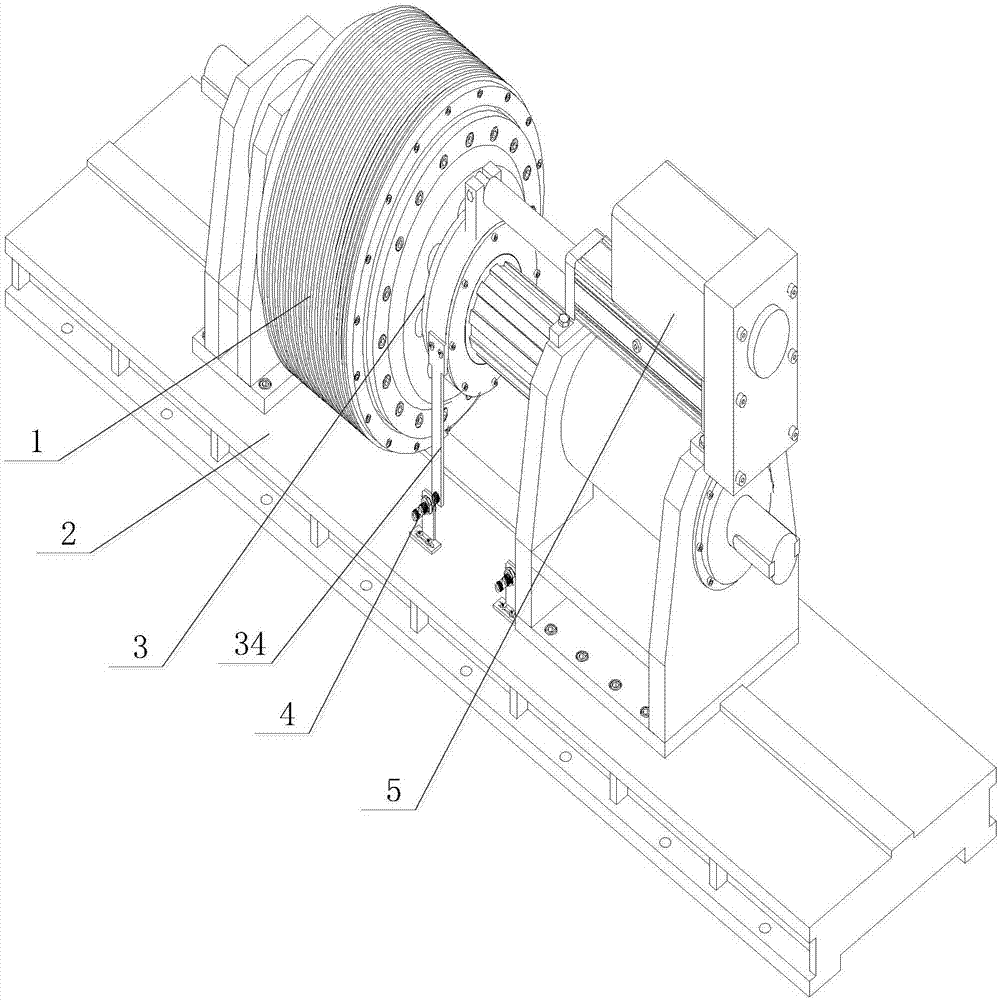
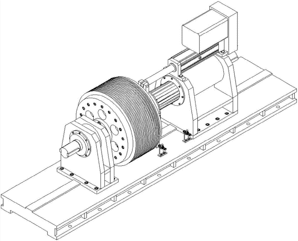
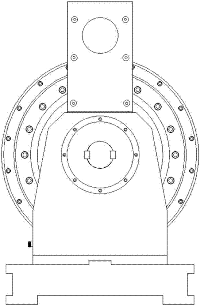
[0052] As shown in the drawings, a speed-regulating permanent magnet eddy current coupling includes: an active rotor mechanism 1, which is mainly composed of an eddy current rotor 6, an active yoke rotor 7, a cooling fin 23, a driving shaft 11 and an active support frame 8 , the eddy current rotor 6 and the active yoke rotor 7 adopt wedge connection, interference fit, to ensure the coaxiality between the eddy current rotor 6 and the active yoke rotor 7, and both ends of the eddy current rotor 6 are bolted to the active yoke rotor 7 connection, so that the two rotors are firmly connected when rotating at high speed, and ensure the reliability of torque transmission; the driven rotor mechanism 3 is mainly composed of permanent magnet 13, magnetic pole inlay 14, driven yoke rotor 15, load shaft 22, driven The support frame 29 and the limit switch ...


PUM


Abstract

The invention discloses a speed-regulating permanent magnet eddy current coupling, comprising: an active rotor mechanism is mainly composed of an eddy current rotor, an active yoke iron rotor, a cooling fin, an active shaft and an active support frame, and the outer part of the active yoke iron rotor is designed with a circumferential Heat sink, the drive shaft is installed on the drive support frame through angular contact bearings; the driven rotor mechanism is mainly composed of permanent magnets, magnetic pole inlays, driven yoke rotors, load shafts, and driven support frames. The permanent magnet section is divided into The upper part is fan-shaped and the lower part is conical; the inner cone surface of the eddy current rotor cooperates with the outer cone surface of the magnetic pole inlay to form the air gap between the driven rotor mechanism and the active rotor mechanism, and the end of the driven yoke iron rotor away from the magnetic pole inlay is connected to the load shaft through a spline , the load shaft is installed on the driven support frame through angular contact bearings; the electric actuator adjusts the meshing area of ​​the eddy current rotor and the magnetic pole inlay. Through the implementation of the invention, soft start, short start time and less heat generation can be realized.

Description

technical field [0001] The invention relates to a permanent magnet eddy current coupling. Background technique [0002] As we all know, the existing resources on the earth are becoming increasingly scarce and will eventually be exhausted. People are constantly exploring and seeking new energy sources. Although remarkable achievements have been made, they cannot replace existing energy sources. Therefore, saving energy and reducing consumption has become a social concern. Especially in the current stage of my country's economic development, energy saving and emission reduction are particularly important. According to statistics, in 2010, there were about 47 million fans and pumps in the country, and their power consumption accounted for more than 30% of the total industrial power consumption in the country. It is too long to damage the motor. Generally, the power of the driving motor is several times the actual rated power, and in some harsh environmental conditions, the vibr...

Claims


Application Information

Patent Timeline
Patent Type & Authority Patents(China)
IPC IPC(8): H02K16/00
Inventor 李贺俊刘永光刘丹
Owner BEIJING SINO POWER RUNZE ENVIRONMENTAL PROTECTIONCO
Why Eureka
Try Eureka