
Method of using infrared eyeball to track and control distance of eyes and screen and system thereof

An eye tracking and distance technology, applied in the direction of instruments, character and pattern recognition, computer components, etc., to achieve the effect of preventing myopia

Inactive Publication Date: 2015-12-30
BEIJING 7INVENSUN TECH
View PDF5 Cites 31 Cited by
  • Summary
  • Abstract
  • Description
  • Claims
  • Application Information

AI Technical Summary

Problems solved by technology

[0004] The purpose of the present invention is to provide a method and system for controlling the distance between the eyes and the screen by using infrared eye tracking, so as to solve the aforementioned problems in the prior art

Method used

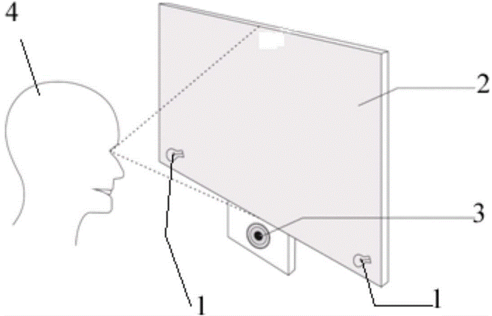
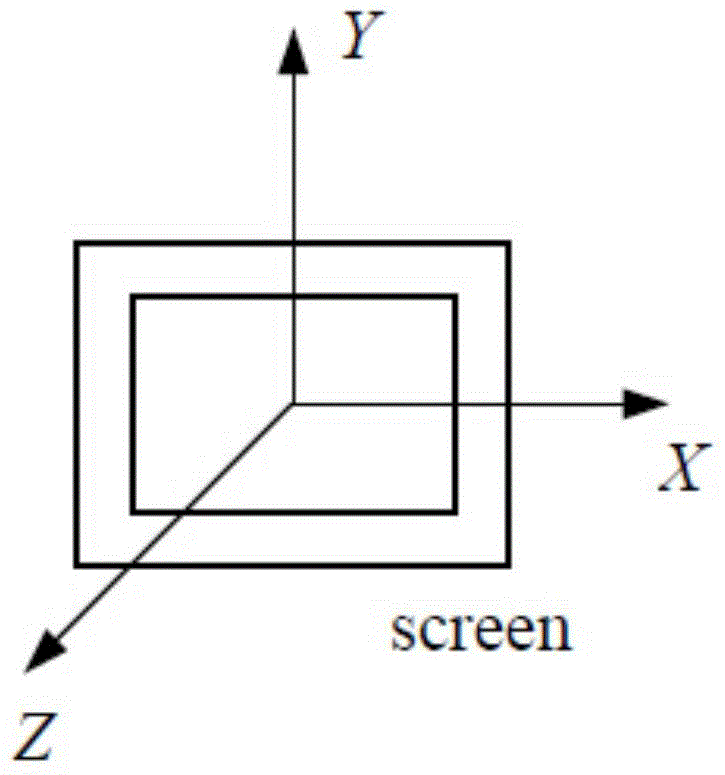
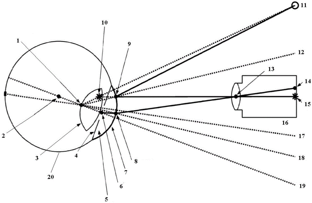

Image

  • Method of using infrared eyeball to track and control distance of eyes and screen and system thereof
  • Method of using infrared eyeball to track and control distance of eyes and screen and system thereof
  • Method of using infrared eyeball to track and control distance of eyes and screen and system thereof

Examples


specific Embodiment approach 2

[0097] Specific embodiment 2. The difference between this embodiment and specific embodiment 1 is that in step S2-3, the calculation of the distance between the user and the target screen uses the calculated pupillary distance of the user's eyes and the preset reference pupillary distance For comparison, specifically:

[0098] Comparing the calculated pupillary distance of the user's eyes with the preset reference pupillary distance, if the calculated pupillary distance exceeds the reference pupillary distance by a certain value, the user is prompted to increase the distance between his eyes and the screen of the electronic device, wherein the The reference pupillary distance is the pupillary distance of the user's eyes set according to the reference distance between the user and the screen of the electronic device.

[0099]The interpupillary distance of the user's eyes is calculated according to the following method: through the face image information obtained by the camera e...

specific Embodiment approach 3

[0101] Specific embodiment 3, the difference between this embodiment and specific embodiment 1 is that in step S2-3, the calculation of the distance between the user and the screen uses the calculated distance between the two light spots and the preset reference two light spots Compare distances, specifically:

[0102] The calculated 2 spot distances are compared with the preset reference 2 spot distances. If the calculated 2 spot distances are greater than the reference 2 spot distances and exceed a certain value, the user is prompted to increase the distance between their eyes and the screen of the electronic device. The distance between the two reference light spots is the distance between the light spots in the eyes of the user set according to the reference distance between the user and the target screen.

[0103] The distance between the two light spots is calculated according to the following method: the infrared light source set around the target screen irradiates the ...

specific Embodiment approach 4

[0106] Embodiment 4. The difference between this embodiment and Embodiment 1 is that in step S2-2, the obtained user face image information is compared with the preset face image data to determine that the user is a child. , restrict the Internet access rights and Internet content of the computer equipment used by children.


PUM


Abstract

The invention discloses a method of using an infrared eyeball to track and control distance of eyes and a screen and a system thereof and relates to the eyeball tracking field. The method comprises the following steps of acquiring whether a user sight point is on a target screen based on an infrared eyeball tracking method; if the user sight point is on the target screen, based on the infrared eyeball tracking method, calculating and acquiring a distance of user eyes and the target screen, and determining whether to give a corresponding prompt according to the distance. In the invention, the infrared eyeball is used to track so that the distance between the user eyes and the target screen is controlled; and whether user eyes are fatigue is determined through combining a user blinking frequency so that an effect of preventing myopic eyes is well reached.

Description

technical field [0001] The invention relates to the field of eye tracking, in particular to a method and system for controlling the distance between eyes and a screen by using infrared eye tracking. Background technique [0002] At present, the method of detecting the distance between the user and the screen of the electronic device is based on an ordinary camera, and then uses the face detection method to perform pupil positioning and pupil distance calculation, and finally uses the distance between the pupil distance and the reference pupil distance preset by the system. The relationship enables the control of the distance between the user's eyes and the screen of the electronic device. [0003] The existing methods for detecting the distance between the user and the screen of an electronic device mainly have the following disadvantages: the existing method cannot determine whether the user's eyes are looking at the screen; cannot accurately detect the distance between the...

Claims


Application Information

Patent Timeline
Patent Type & Authority Applications(China)
IPC IPC(8): G06K9/00
Inventor 彭凡沈丁成
Owner BEIJING 7INVENSUN TECH
Learn More