
Method for detecting coupling of optical module and optical fibers

A technology of optical fiber coupling and detection method, applied in the field of optical communication, can solve the problems of low efficiency of optical module and optical fiber coupling detection method, etc.

Active Publication Date: 2015-12-30
HISENSE & JONHON OPTICAL ELECTRICAL TECH CO LTD
View PDF5 Cites 5 Cited by
  • Summary
  • Abstract
  • Description
  • Claims
  • Application Information

AI Technical Summary

Problems solved by technology

[0006] The purpose of the present invention is to provide a method for coupling detection of optical modules and optical fibers to solve the technical problem of low efficiency in the coupling detection methods of optical modules and optical fibers in the prior art

Method used


Image

  • Method for detecting coupling of optical module and optical fibers
  • Method for detecting coupling of optical module and optical fibers
  • Method for detecting coupling of optical module and optical fibers

Examples


Embodiment Construction

[0023] In order to make the purpose, technical solutions and advantages of the present invention clearer, the present invention will be further described in detail below in conjunction with the accompanying drawings. Obviously, the described embodiments are only some of the embodiments of the present invention, rather than all of them. Based on the embodiments of the present invention, all other embodiments obtained by persons of ordinary skill in the art without making creative efforts belong to the protection scope of the present invention.

[0024] The technical solutions provided by the embodiments of the present invention will be described in detail below in conjunction with the accompanying drawings.

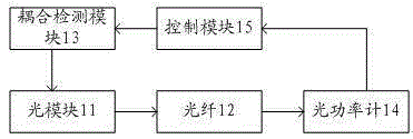
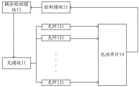
[0025] The optical module and optical fiber coupling detection method proposed in the embodiment of the present invention is based on figure 1 The shown optical module and optical fiber coupling detection device, the device includes an optical module 11, an optical fiber 1...


PUM


Abstract

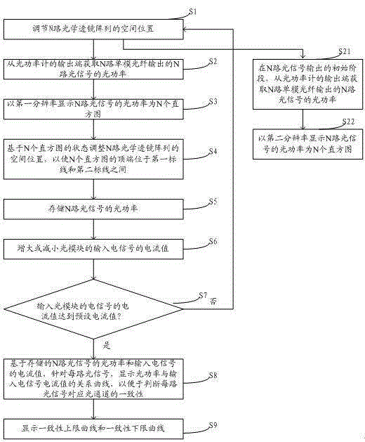
The invention discloses a method for detecting coupling of an optical module and optical fibers. The technical problem that a detection mode for coupling of the optical module and the optical fibers is low in efficiency is solved. The method includes the steps that the space positions of N paths of optical lens arrays are adjusted; the optical powers of N paths of optical signals output by the N paths of single-mode optical fibers are acquired from the output end of an optical power meter; the optical powers of the N paths of optical signals are displayed as N histograms with the first resolution, and the optical powers and the heights of the histograms are in a direct proportion relation; the space positions of the N paths of optical lens arrays are adjusted based on the states of the N histograms, and then the top ends of the N histograms are located between a first marked line and a second marked line; the first marked line and the second marked line are graphical display for the allowed minimal power value and the allowed maximal power value, and when the top ends, corresponding to the histograms, of the N paths of optical signals are located between the first marked line and the second marked line, the coupling degree of the optical module and the optical fibers is optimal. Complex manual recording and comparison steps are omitted in a visual mode, and detection efficiency is improved.

Description

technical field [0001] The invention relates to the technical field of optical communication, in particular to a coupling detection method for an optical module and an optical fiber. Background technique [0002] In the existing optical communication technology, the optical signal is used as the carrier of information, which can transmit information at high speed, long time and reliably; while the optical module is the core component in the field of optical communication technology, the coupling between its optical element and the optical fiber as the transmission path The effect directly affects the intensity of the output optical signal and the quality of the optical signal, so the coupling effect between the optical module and the optical fiber becomes a key factor affecting information transmission. [0003] In order to make the connection between the optical module and the optical fiber have an optimal coupling degree, before the optical module leaves the factory, it is...

Claims


Application Information

Patent Timeline
IPC IPC(8): G02B6/42
CPCG02B6/4204G02B6/4225
Inventor 韩泽李建孟姜瑜斐曲业飞
Owner HISENSE & JONHON OPTICAL ELECTRICAL TECH CO LTD
Learn More